Use of the SSD1306 display by the Micro:bit board
Tutorial plan
1- What is the SSD1306 display ?
2- How Micro:bit board displays text in SSD1306 display ?
3- The necessary components to use the SSD1306 display by the Micro:bit card
4- Micro:bit board wiring diagram with SSD1306 display
5- Programming the Micro:bit board with Makecode to display text in the SSD1306 display
What is the SSD1306 display ?
The SSD1306 display is a type of OLED (Organic Light-Emitting Diode) display that uses the SSD1306 driver chip. It's commonly used in various electronic projects and devices to showcase information. The display itself is made up of individual pixels that emit light, allowing for high contrast ratios and vibrant colors.
The SSD1306 controller chip manages the pixels on the display. It's known for its compatibility with microcontrollers like Micro:bit board, making it a popular choice among hobbyists and developers for its ease of use and versatility.
Applications of SSD1306 displays range from small handheld devices like smartwatches, fitness trackers, and portable meters to larger informational displays in IoT (Internet of Things) devices, where compactness, low power consumption, and visual quality are essential.
How Micro:bit board displays text in SSD1306 display ?
The Micro:bit can display text on an SSD1306 display using libraries like the muselab-oled-v2. Here's a general guide on how you might achieve this:
1- Setup Hardware: Connect the SSD1306 display to the Micro:bit using the appropriate connections (such as I2C or SPI). Ensure the connections are correct, and power both the Micro:bit and the display.
2- Include Libraries and Initialize: Include the "muselab-oled-v2" library in your code and initialize the display.
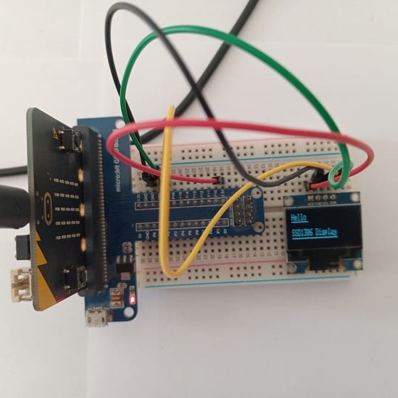
3- Upload and Run: Upload the code to your Micro:bit board. You should see the text displayed on your SSD1306 screen.
Remember to adjust the pin configurations and any library-specific settings according to your specific hardware connections and requirements.
The necessary components to use the SSD1306 display by the Micro:bit card
To use a SSD1306 display with the Micro:bit board, you'll need the following components:
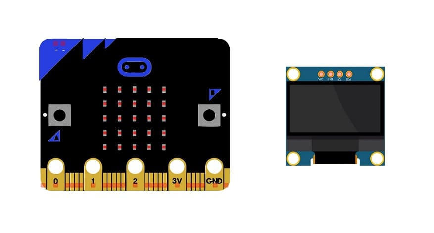
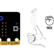
Micro:bit board:

The Micro:bit board is a small, programmable microcontroller board designed for education and beginner-friendly coding projects. It was developed by the BBC, in collaboration with various partners, as a tool to introduce young people to programming and electronics.
The GPIO expansion card for the Micro:bit card

The GPIO expansion board for the Micro:bit board expands the capabilities of the Micro:bit board by adding more input/output (GPIO) pins and additional functionality.
SSD1306 display:
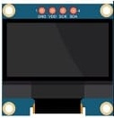
The SSD1306 display is a type of OLED (Organic Light-Emitting Diode) display that uses the SSD1306 driver chip.
Jumper Wires:

To make the physical connections between the components.
Breadboard:

A breadboard is a useful tool for creating temporary electronic circuits. It allows you to connect components without soldering .
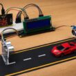
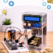
Micro:bit board wiring diagram with SSD1306 display
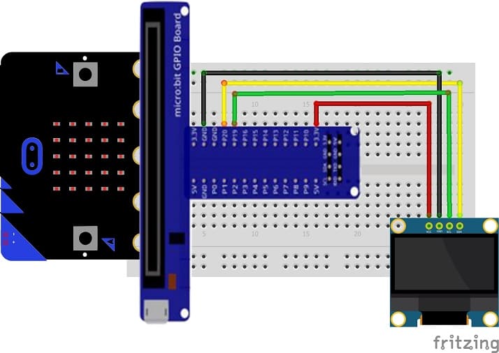
Connect the SSD1306 Display to your Micro:bit as follows:
1- Connect the SDA (data line) of the SSD1306 display to P20 pin of the Micro:bit board.
2- Connect the SCL (clock line) of the SSD1306 display to P19 pin of the Micro:bit board.
3- Connect the VCC pin of the SSD1306 display to the 3.3V pin of the Micro:bit board.
4- Connect the GND pin of the SSD1306 display to GND pin of the Micro:bit board.
Programming the Micro:bit board with Makecode to display text in the SSD1306 display
Programming the Micro:bit board to display text on the SSD1306 display using MakeCode involves using the blocks-based programming environment provided by MakeCode. Here are step-by-step instructions:
1- Go to the MakeCode website: https://makecode.microbit.org/
2- Click on "New Project" to create a new project.
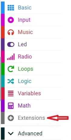
3- Look for "Extensions" and click on it.
4- In the search box, type "muselab-oled-v2" to find the OLED extension.
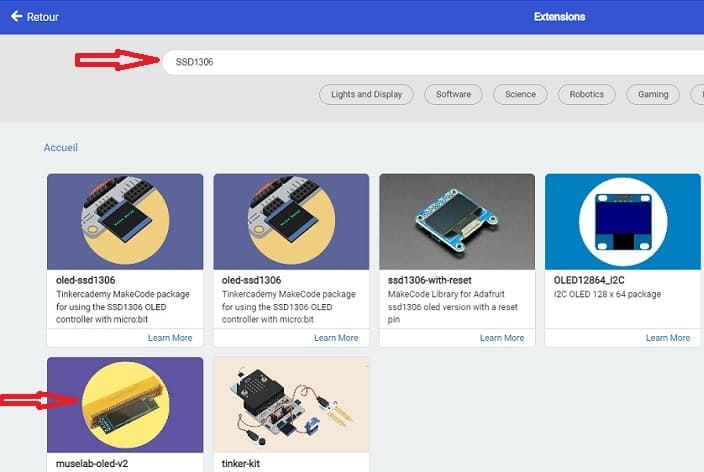
5- Click on the "SSD1306" extension to add it to your project.
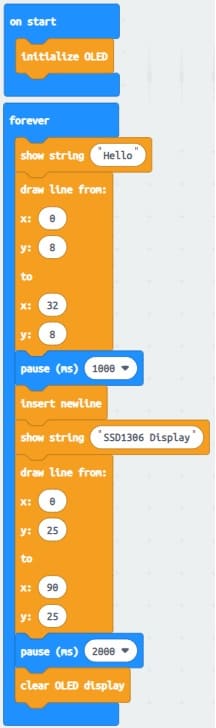
6- In the "on start" block, drag and drop the "OLED initialize" block from the SSD1306 extension category. This block initializes the SSD1306 display.
7- To display text on the SSD1306 display, go to the "OLED" category in the toolbox.
8- Drag and drop the "OLED show string" block into your workspace.
9- Enter the text you want to display in the block.
10- Drag and drop the "draw line from" block into your workspace to draw a line on SSD1306 display
11- Once your code is ready, click on the "Download" button to download the hex file onto the Micro:bit board to flash the program.
Here's a simple example code:
0 comment
Leave a comment
Passion for robotics

Recent tutorials


Robotics workshop

Polpular tutorials


Making robots

Most commented tutorials


Robotic arm

Categories
Smart Home