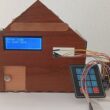
Use a 4×4 matrix keyboard with an ESP32 board
Tutorial plan
1- What is a 4x4 matrix keyboard ?
2- How ESP32 board displays 4x4 matrix keypad data in SSD1306 display ?
3- Components Needed to use a 4x4 matrix keyboard with an ESP32 board
4- Wiring the Components:
5- Programming ESP32 with Micropython
What is a 4x4 matrix keyboard ?
A 4x4 matrix keyboard is a type of keyboard arrangement that contains 16 keys (4 rows and 4 columns). It is a cost-effective and space-saving way to implement a keyboard input for electronic projects, such as microcontrollers (like Arduino, ESP32, etc.), security systems, or home automation devices.
Structure of a 4x4 Matrix Keyboard
The matrix is arranged in a grid of rows and columns, each containing 4 keys. Here's how it's typically organized:
Rows (R1, R2, R3, R4): 4 horizontal connections.
Columns (C1, C2, C3, C4): 4 vertical connections.
Each key is placed at the intersection of a row and a column. When a key is pressed, it connects a specific row and column, and this is how the pressed key is identified.
Key Features:
16 keys: A 4x4 matrix keyboard has a total of 16 physical buttons, arranged in 4 rows and 4 columns.
Wired in a matrix: Instead of connecting each key to a separate pin on the microcontroller, the keys are arranged in a matrix to minimize the number of input/output (I/O) pins needed. Only 8 pins are required—4 for the rows and 4 for the columns.
Scanning Process: The microcontroller scans the keyboard by sending signals to the rows and reading the columns (or vice versa). When a button is pressed, it closes the circuit between a row and a column, allowing the microcontroller to detect which key was pressed.
Advantages:
Reduced Pin Usage: Instead of needing 16 pins to connect each individual key, the matrix structure uses only 8 pins (4 for rows and 4 for columns).
Compact: The matrix layout allows for compact designs, making it ideal for embedded systems or devices with limited space.
Cost-Effective: Using fewer pins for more keys makes matrix keyboards cheaper and easier to implement.
How It Works:
The rows are typically set to a LOW (ground) state one at a time.
The columns are read for a HIGH state.
When a key is pressed, it connects a row to a column, allowing the system to detect which key was pressed based on the row and column combination.
How ESP32 board displays 4x4 matrix keypad data in SSD1306 display ?
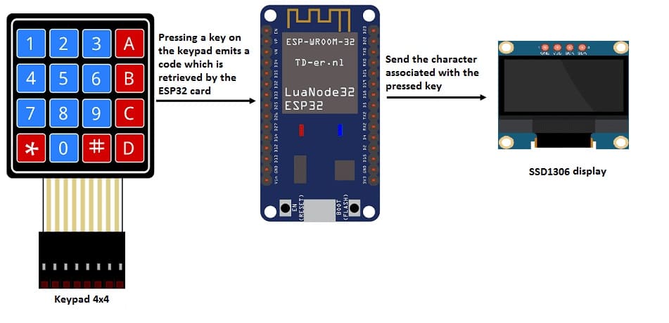
Keypad Scanning: The ESP32 scans the 4x4 matrix keypad to detect which key is pressed.
Display Update: When a key is pressed, the character corresponding to that key is displayed on the SSD1306 OLED display. The screen is cleared first to ensure the display updates with the correct information.
Feedback to User: The user sees the pressed key on the display in real-time, which could be part of a larger interface, such as a menu, password input, or control panel.
Components Needed to use a 4x4 matrix keyboard with an ESP32 board
To use a 4x4 matrix keyboard with an ESP32 board and an SSD1360 display, you will need several key components, each with a specific role.
Here's a description of the components and their functions:
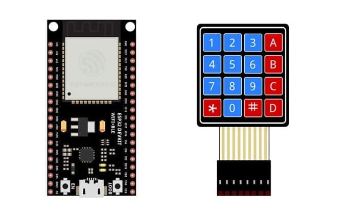
ESP32 Board
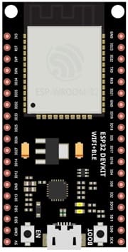
The ESP32 is the microcontroller that handles all the logic and control of the system. It reads input from the 4x4 matrix keyboard, processes the input, and sends the relevant output to the SSD1360 display or other connected devices.
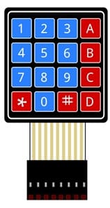
4x4 Matrix Keyboard
The 4x4 matrix keyboard acts as the input device. It allows the user to press keys to send commands or data to the ESP32. This is typically used for entering PINs, controlling devices, or interacting with the system.
SSD1360 OLED Display
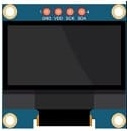
The SSD1360 is an OLED display controller that drives the visual output on a small, high-resolution screen. It is typically used to display text, graphics, or menus in embedded projects.
Jumper Wires
Jumper wires are used to physically connect the ESP32 board, the 4x4 matrix keyboard, and the SSD1360 display. These wires transfer electrical signals between the components, allowing them to communicate.
Breadboard:
A breadboard can be used to create a temporary circuit for testing and prototyping.
Wiring the Components
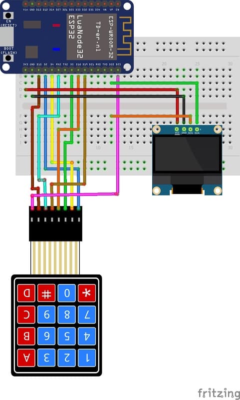
4x4 Matrix Keypad to ESP32:
We connect the 8 outputs of the keypad to the 8 pins of the ESP32 card following this order: D2, D4, D5, D18, D19, D16, D15 and D23.
SSD1306 OLED Display to ESP32:
SDA (data line) to a GPIO pin (e.g., GPIO 21).
SCL (clock line) to another GPIO pin (e.g., GPIO 22).
VCC to the 3.3V or 5V pin on the ESP32 (depending on the display's voltage requirement).
GND to the ground pin on the ESP32.
Programming ESP32 with Micropython
Here’s an example code that shows how the ESP32 reads data from the 4x4 matrix keypad and displays it on an SSD1306 OLED display:
Note: the following library must be imported: ssd1306.py To control the SSD1306 OLED display
|
1 2 3 4 5 6 7 8 9 10 11 12 13 14 15 16 17 18 19 20 21 22 23 24 25 26 27 28 29 30 31 32 33 34 35 36 37 38 39 40 41 42 43 44 45 46 47 48 49 50 51 52 53 54 55 56 57 58 59 60 61 62 63 64 65 |
from machine import Pin,I2C import ssd1306 from time import sleep import utime import machine WIDTH = 128 HEIGHT = 64 i2c = I2C(scl=Pin(22), sda=Pin(21)) #Init i2c oled=ssd1306.SSD1306_I2C(128,64,i2c,0x3c) # CONSTANTS KEY_UP = const(0) KEY_DOWN = const(1) keys = [['1', '2', '3', 'A'], ['4', '5', '6', 'B'], ['7', '8', '9', 'C'], ['*', '0', '#', 'D']] # Pin names for Pico cols = [19,16,15,23] rows = [2,4,5,18] # set pins for rows as outputs row_pins = [Pin(pin_name, mode=Pin.OUT) for pin_name in rows] # set pins for cols as inputs col_pins = [Pin(pin_name, mode=Pin.IN, pull=Pin.PULL_DOWN) for pin_name in cols] def init(): for row in range(0,4): for col in range(0,4): row_pins[row].value(0) def scan(row, col): """ scan the keypad """ # set the current column to high row_pins[row].value(1) key = None # check for keypressed events if col_pins[col].value() == KEY_DOWN: key = KEY_DOWN if col_pins[col].value() == KEY_UP: key = KEY_UP row_pins[row].value(0) # return the key state return key print("starting") # set all the columns to low init() while True: oled.fill(0) for row in range(4): for col in range(4): key = scan(row, col) if key == KEY_DOWN: oled.text("Key Pressed: ",10,0) print("Key Pressed", keys[row][col]) oled.text(keys[row][col], 55, 30) # display the character associated with the key press oled.show() last_key_press = keys[row][col] |

