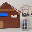
Turn on two LEDs using radio communication between two Micro:bit boards
Tutorial plan
1- Introduction to the Micro:bit Board Radio Module
2- Controlling two LEDs by radio communication from the Micro:bit board
3- The components needed to control two LEDs by Micro:bit
4- Mounting the Micro:bit board with an two LEDs
Introduction to the Micro:bit Board Radio Module
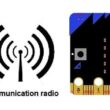
The BBC micro:bit is a pocket-sized computer board designed for educational purposes. It has a built-in radio module that allows micro:bit boards to communicate with each other wirelessly. The radio module on the micro:bit uses Bluetooth Low Energy (BLE) technology, which enables short-range communication between devices.
The radio module on the micro:bit board allows for wireless communication and data transfer. It operates on the 2.4 GHz frequency band and supports a range of up to 30 meters (or about 100 feet) in an open space environment. The micro:bit radio module can be used for various applications, such as creating interactive games, sending messages between devices, or building remote-controlled projects.
To use the radio module on the micro:bit, you can program it using the micro:bit's programming environments, such as the Microsoft MakeCode editor or the MicroPython programming language. These environments provide blocks or functions specifically designed to control the radio module and enable communication between micro:bit boards.
By utilizing the radio module, you can establish a communication link between multiple micro:bit boards, allowing them to exchange data, coordinate actions, or create collaborative projects. It's a powerful feature that adds interactivity and connectivity to your micro:bit projects.
Controlling an two LEDs by radio communication from the Micro:bit board
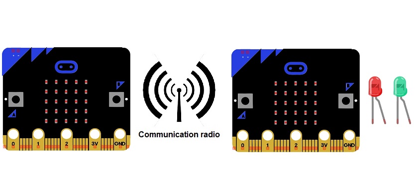
To control an two LEDs using radio communication from one micro:bit board to another, you'll need two micro:bit boards—one acting as a transmitter and the other as a receiver. Here's a step-by-step guide on how to accomplish this:
Transmitter (Micro:bit A):
1- Connect two LEDs to micro:bit's GPIO pins (for example, P0 for red LED and P1 for green LED). Ensure to use a current-limiting resistor (e.g., 220-470 ohms) in series with the LED.
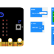
2- Open the Microsoft MakeCode editor.
3- Write the following code to send radio messages:
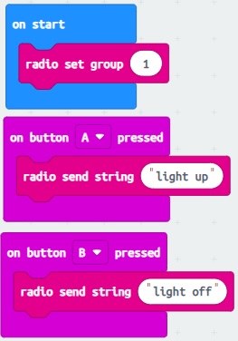
4- Download the code to the micro:bit (A) and disconnect it from the computer.
Receiver (Micro:bit B):
1- Connect another micro:bit board to your computer and open the programming environment.
2- Write the following code to receive radio messages and control the two LEDs:
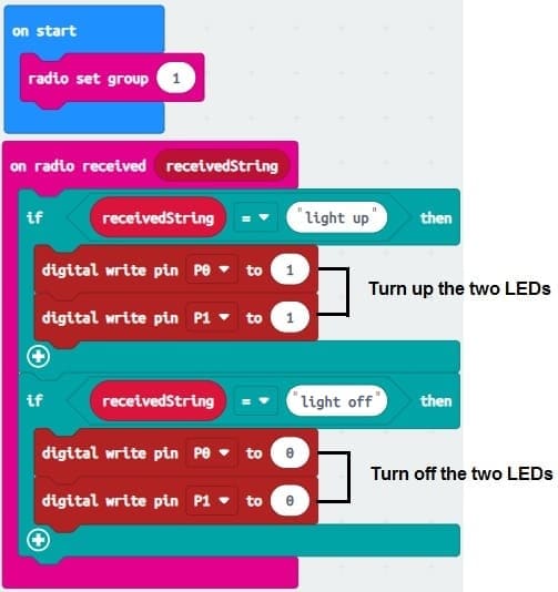
3- Download the code to the micro:bit (B) and disconnect it from the computer.
Now, whenever you press button A on the transmitter micro:bit (A), it will turn on the two LEDs connected to P0 micro:bit (B).
whenever you press button B on the transmitter micro:bit (A), it will turn off the two LEDs connected to P0 micro:bit (B).
The components needed to control two LED by Micro:bit
To control an LED using a Micro:bit, you will need the following components:
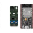
Two Micro:bit board

The Micro:bit is a small programmable development board with an ARM microcontroller. It has built-in LED indicators and GPIO (General Purpose Input/Output) pins that can be used to control external components like an LED.
The GPIO expansion card for the Micro:bit card

The GPIO expansion board for the Micro:bit board expands the capabilities of the Micro:bit board by adding more input/output (GPIO) pins and additional functionality.
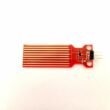
LEDs: You'll need two LEDs of your choice. LEDs come in different colors, so you can select the colors that suit your project. 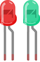
Resistors: LEDs require current-limiting resistors to prevent excessive current flow and protect them from damage. The value of the resistor depends on the forward voltage and forward current specifications of your LEDs. A commonly used resistor value for LEDs is around 220-330 ohms. 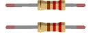
Jumper wires

You will need jumper wires to connect the Micro:bit to the LED and the current-limiting resistor. Make sure you choose the appropriate type of jumper wires (e.g., male-to-male, male-to-female, or female-to-female) based on your specific setup.
Test plate

The breadboard is a common tool used in robotics and electronics to create circuit prototypes and temporary connections. It makes it easy to test and connect electronic components together without having to solder the connections.
Once you have gathered these components, you can properly connect them and program the Micro:bit board to control the LED as needed. Be sure to follow good connection and safety practices when handling electronic components.
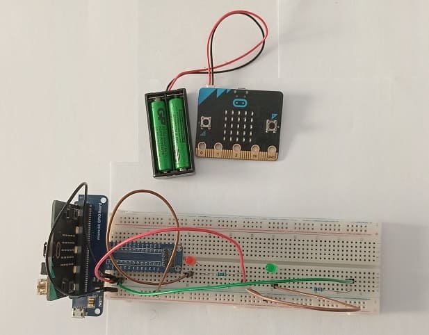
Mounting the Micro:bit board with two LEDs
Once you have these components, you can follow these steps to control the LEDs with a Micro:bit:
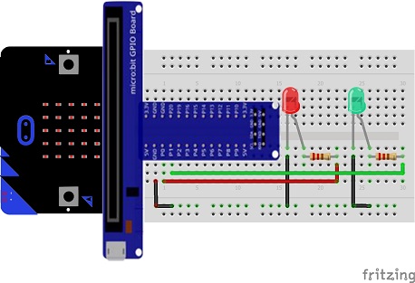
1- Connect the red LED:
- Connect the longer leg (anode) of the LED to one end of the resistor.
- Connect the other end of the resistor to P0 pin of the Micro:bit's GPIO pins (Pin 0).
- Connect the shorter leg (cathode) of the LED to the Micro:bit's ground (GND) pin.
2- Connect the green LED: repeat the same connections as for the red LED, but use a different GPIO pin (Pin 1) on the Micro:bit.
0 comment
Leave a comment
Passion for robotics

Recent tutorials
Robotics workshop

Polpular tutorials


Making robots

Most commented tutorials
Robotic arm

Categories
Smart Home