Turn on RGB LED module by Micro:bit
Tutorial plan
1- Role of RGB LED module in robotics
2- The components needed to control RGB LED module by Micro:bit
3- Mounting the Micro:bit board with RGB LED module
4- Color variation of the RGB LED module by the Micro:bit card
5- Turn on RGB LED module using the buttons on the Micro:bit board
Role of RGB LED module in robotics
RGB LED modules play a significant role in robotics by providing versatile and customizable lighting solutions. Here are some key roles of RGB LED modules in robotics:
Status Indicators: RGB LEDs can serve as status indicators on robots, providing visual feedback to users and operators. Different colors can be used to indicate various robot states, such as active, idle, error, or charging.
Color Detection: RGB LEDs can be used in conjunction with color sensors to detect and differentiate colors in the environment. This can be useful in applications like sorting objects by color or recognizing specific markers for navigation.
Human-Robot Interaction: RGB LEDs can be used to communicate with humans more effectively. For example, a robot can change the color and intensity of its LEDs to convey emotions or intentions, making the interaction more intuitive.
Customization: The color and lighting patterns of RGB LED modules can be customized to match the robot's aesthetics or branding. This personalization can help distinguish robots in different applications and make them more appealing.
Navigation and Wayfinding: Robots can use RGB LEDs to create visual markers for navigation. These markers can help the robot identify its position and orientation within an environment or follow specific paths.
Interactive Behaviors: RGB LEDs can be used to create engaging and interactive behaviors in robots. For example, a robot might change colors and patterns in response to voice commands or gestures, enhancing the user experience.
Safety and Visibility: RGB LEDs can improve the visibility and safety of robots, especially in low-light conditions. They can serve as warning lights or be used to signal the presence of a robot in a particular area.
Aesthetics and Artistic Expression: Some robots are designed for artistic or entertainment purposes. RGB LEDs allow for creative lighting effects and artistic displays, enhancing the visual appeal of these robots.
Teaching and Education: In educational robotics, RGB LED modules can be used to teach students about color theory, electronics, and programming. They provide a hands-on way to explore these concepts.
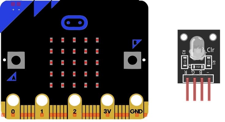
The components needed to control RGB LED module by Micro:bit
To control an RGB LED module with a Micro:bit, you will need a few components and some additional materials. Here's a list of the components you'll need:
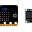
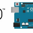
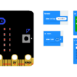
Micro:bit Board:
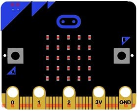
The Micro:bit is the central controller for your project. It has input/output pins that you'll use to control the RGB LED module.
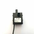
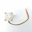
RGB LED Module:
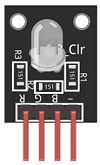
You will need an RGB LED module. These modules typically have four pins: one for the common anode (positive), and three for the red, green, and blue color channels.
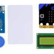
The GPIO expansion card for the Micro:bit card

The GPIO expansion board for the Micro:bit board expands the capabilities of the Micro:bit board by adding more input/output (GPIO) pins and additional functionality.
Connecting Wires:

You'll need jumper wires or connecting cables to make the necessary electrical connections between the Micro:bit and the RGB LED module.
Breadboard (Optional):

A breadboard can be useful for creating temporary connections without soldering. It simplifies the wiring process.
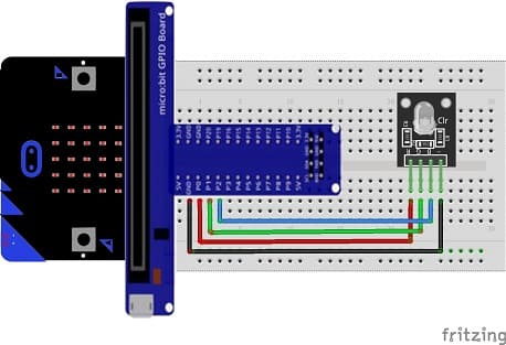
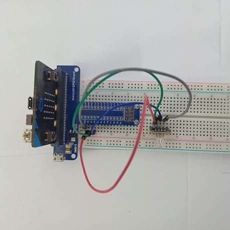
Mounting the Micro:bit board with RGB LED module
To mount a Micro:bit board with an RGB LED module, you will need to physically connect the Micro:bit to the RGB LED module using wires. Here are the steps to mount the Micro:bit with an RGB LED module:
1- Prepare Your Components:
- Ensure you have a Micro:bit board and an RGB LED module.
- Prepare the connecting wires. You will need wires to connect the Micro:bit to the RGB LED module.
2- Identify the Pins:
- On the Micro:bit, identify the pins you will use for connecting to the RGB LED module. Common choices include pins P0, P1, and P2 for controlling the RGB LED's red, green, and blue channels.
- On the RGB LED module, identify the pins for the common anode and the individual cathodes for red, green, and blue.
3- Make the Connections:
- Connect the pin R(red) of RGB LED module to pin P0 of Micro:bit
- Connect the pin G(Green) of RGB LED module to pin P1 of Micro:bit
- Connect the pin B(Blue) of RGB LED module to pin P2 of Micro:bit
- Connect the pin GND of RGB LED module to pin GND of Micro:bit
Color variation of the RGB LED module by the Micro:bit card
To create a color variation of an RGB LED module using the Micro:bit card and MakeCode, you can write a simple program that changes the colors in a loop. Here's how you can do it:
1- Open MakeCode: Visit the MakeCode website (https://makecode.microbit.org/).
2- Create a New Project: Start a new MakeCode project for your Micro:bit.
3- Write the Color Variation Code:
Here's a simple example code to create a color variation that cycles through different colors:
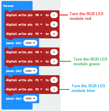
This code will cycle through the colors red, green, blue, orange, and purple, with a one-second pause between color changes. You can adjust the basic.pause value to control the speed of the color variation.
4- Download and Transfer the Code: Click the "Download" button to transfer the code to your Micro:bit.
5- Run the Program: The Micro:bit will now display a color variation as programmed.
This code will continuously cycle through the defined colors on your RGB LED module. You can customize the list of colors or add more colors to create different visual effects. Adjust the timing and colors to suit your preferences.
Turn on RGB LED module using the buttons on the Micro:bit board
To turn on an RGB LED module using the buttons on the Micro:bit board and MakeCode, you can create a simple program that toggles the LED module's state when a button is pressed. Here's how you can do it:
1- Open MakeCode: Visit the MakeCode website (https://makecode.microbit.org/).
2- Create a New Project: Start a new MakeCode project for your Micro:bit.
3- Write the Button-Controlled Code: Here's a simple example code to turn on and off the RGB LED module using the A and B buttons:
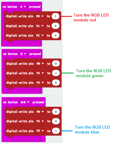
In this example, button A lights the RGB LED module red, button B lights it green, and pressing both buttons (A+B) causes the RGB LED module to light blue.
4- Download and Transfer the Code: click the "Download" button to transfer the code to your Micro:bit.
5- Run the Program: Press buttons A and B to see the RGB LED module light up in red, green and blue.
This code allows you to use the A and B buttons on your Micro:bit to control the RGB LED module, turning it on and off with different colors. You can customize the colors and behavior to suit your preferences and application.
0 comment
Leave a comment
Passion for robotics

Recent tutorials
Robotics workshop

Polpular tutorials


Making robots

Most commented tutorials
Robotic arm

Categories
Smart Home