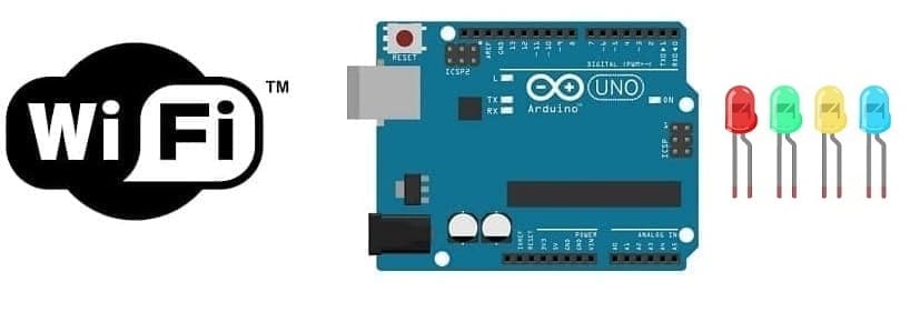
Turn on four LEDs connected to Arduino UNO via WIFI
Tutorial plan
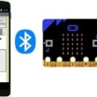
1- The difference between WIFI and Bluetooth
2- The role of WIFI in robotics
2- The Arduino UNO board and Wifi
3- Presentation of the ESP8266 WIFI module
4- Light up four LEDs connected to the Arduino UNO board via WIFI using the ESP8266 module
5- The components needed to control four LEDs by the Arduino UNO board and ESP8266 module
6- Mounting the Arduino UNO board with the ESP8266 Module and four LEDs
The difference between WIFI and Bluetooth
Wi-Fi and Bluetooth are both wireless communication technologies, but they serve different purposes and have distinct characteristics. Here are the key differences between Wi-Fi and Bluetooth:
1- Purpose:
- Wi-Fi (Wireless Fidelity): Wi-Fi is primarily designed for high-speed data transmission over relatively long distances. It is commonly used for connecting devices to the internet, local area networks (LANs), and to each other for tasks like file sharing and media streaming.
2- Bluetooth: Bluetooth is designed for short-range wireless communication between devices. It is mainly used for connecting peripherals like keyboards, mice, headphones, speakers, and for transferring smaller files between devices such as smartphones, tablets, and laptops.
2- Range:
- Wi-Fi: Wi-Fi typically has a longer range compared to Bluetooth. Wi-Fi signals can cover large areas, depending on the router's power and the presence of obstacles.
- Bluetooth: Bluetooth has a shorter range, usually up to about 30 meters (100 feet). However, this range can vary depending on the Bluetooth version and the specific devices involved.
3- Data Transfer Rate:
- Wi-Fi: Wi-Fi offers much higher data transfer rates than Bluetooth. Modern Wi-Fi standards, like Wi-Fi 6 (802.11ax), can provide speeds of several gigabits per second, making it suitable for streaming high-definition video and fast internet access.
- Bluetooth: Bluetooth offers lower data transfer rates compared to Wi-Fi. The latest Bluetooth 5.x standard provides speeds of up to 2 Mbps, which is sufficient for most audio streaming and file transfers but not ideal for high-bandwidth tasks.
4- Power Consumption:
- Wi-Fi: Wi-Fi tends to consume more power, which is why devices like smartphones and laptops have limited battery life when actively using Wi-Fi connections.
- Bluetooth: Bluetooth is designed to be more power-efficient, making it suitable for battery-operated devices like wireless headphones and fitness trackers. Bluetooth Low Energy (BLE) is a variant of Bluetooth designed specifically for low-power applications.
5- Use Cases:
- Wi-Fi: Wi-Fi is commonly used for internet access, online gaming, streaming media, and connecting multiple devices to a network.
- Bluetooth: Bluetooth is often used for connecting accessories like headphones, speakers, keyboards, and mice to computers and mobile devices, as well as for tasks like transferring photos and files between smartphones.
In summary, Wi-Fi is better suited for high-speed, long-range wireless data transmission, while Bluetooth is designed for short-range connections between devices, emphasizing low power consumption and compatibility with various peripherals. The choice between Wi-Fi and Bluetooth depends on the specific use case and requirements of the devices involved.
The role of WIFI in robotics
Wi-Fi (Wireless Fidelity) plays a significant role in robotics by enabling wireless communication between robots and other devices, such as computers, smartphones, and sensors. This wireless technology offers several advantages for robotic applications:
Remote Control: Wi-Fi allows operators or users to remotely control robots over a network connection. This is particularly useful in scenarios where direct physical access to the robot is difficult or dangerous, such as in search and rescue missions, space exploration, or hazardous environments.
Data Transfer: Robots often require real-time data exchange with external systems, such as receiving sensor data or sending telemetry information to a central control station. Wi-Fi provides a high-speed, wireless connection for efficient data transfer.
Sensor Integration: Wi-Fi can connect robots to a wide range of sensors and cameras. This connectivity allows robots to gather information from their surroundings and make informed decisions, enhancing their perception and navigation capabilities.
Software Updates: Robots can receive software updates and patches over a Wi-Fi connection, ensuring that they always have the latest features, bug fixes, and security enhancements.
Cloud Computing: Wi-Fi connectivity can facilitate the integration of robots with cloud-based services. Robots can offload resource-intensive tasks to remote servers, enabling them to perform complex computations, machine learning, and data analysis in real-time.
Collaboration: Multiple robots can communicate with each other over a Wi-Fi network, enabling collaborative tasks. For example, in warehouse automation, robots can coordinate their movements to optimize workflow and efficiency.
Monitoring and Maintenance: Wi-Fi enables remote monitoring of robot status and performance. This is valuable for proactive maintenance and troubleshooting, reducing downtime.
Human-Robot Interaction: Wi-Fi connectivity supports human-robot interaction by enabling robots to interact with users through smartphones, tablets, or other portable devices. This can be useful in applications like home automation, healthcare, and education.
Simultaneous Localization and Mapping (SLAM): Wi-Fi can assist in SLAM algorithms, which help robots map and navigate unknown environments. By using Wi-Fi signals as additional reference points, robots can improve their localization accuracy.
Security: While Wi-Fi offers convenience, it also raises security concerns, especially in critical robotic applications. Proper security measures, including encryption, authentication, and access control, are crucial to protect against unauthorized access and potential cyberattacks.
The Arduino UNO board and Wifi
The Arduino Uno board is a popular microcontroller development board used for various electronics and embedded systems projects. While the Arduino Uno itself doesn't have built-in Wi-Fi capability, you can add Wi-Fi connectivity to your Arduino Uno projects using various add-on modules or shields. Here's how you can do that:
Wi-Fi Shields: Arduino offers Wi-Fi shields that you can plug into the Uno to add Wi-Fi connectivity. One common example is the Arduino Wi-Fi Shield, which is based on the ESP8266 or similar Wi-Fi modules. These shields provide a simple way to connect your Arduino Uno to a Wi-Fi network and communicate over the internet.
ESP8266 Module: You can use an ESP8266 module, such as the ESP-01 or ESP-12, to add Wi-Fi to your Arduino Uno. The ESP8266 is a low-cost and versatile Wi-Fi module that can be programmed using the Arduino IDE. You can connect it to the Uno using UART communication (TX and RX pins).
ESP32 Module: The ESP32 is another popular Wi-Fi and Bluetooth module that can be used with the Arduino IDE. It offers more processing power and features compared to the ESP8266. You can connect an ESP32 module to your Arduino Uno via UART or SPI, depending on your project requirements.
Arduino-Compatible Boards: There are Arduino-compatible boards with built-in Wi-Fi capabilities, such as the Arduino MKR series (e.g., Arduino MKR1000, MKR1010) and Arduino Nano 33 IoT. These boards are based on microcontrollers with integrated Wi-Fi modules, making it easier to develop Wi-Fi-enabled projects.
To use Wi-Fi with your Arduino Uno, follow these general steps:
Choose a Wi-Fi Module or Shield: Select the Wi-Fi module or shield that best fits your project's requirements and budget.
1- Wiring: Connect the selected module or shield to the Arduino Uno following the provided documentation or pinout diagrams.
2- Install Libraries: Install the necessary libraries in the Arduino IDE to program and control the Wi-Fi module. Most Wi-Fi modules have specific libraries that make it easier to interface with them.
3- Programming: Write your Arduino sketch (code) to configure and control the Wi-Fi module. This includes setting up the Wi-Fi network credentials (SSID and password), connecting to Wi-Fi, and defining how your Uno will communicate over Wi-Fi (e.g., HTTP requests, MQTT, etc.).
4- Testing: Upload your sketch to the Arduino Uno, and test the Wi-Fi functionality to ensure it works as intended. You can send and receive data over the Wi-Fi network, connect to web services, or control your Arduino remotely.
Presentation of the ESP8266 WIFI module
The ESP8266 is a low-cost and highly versatile Wi-Fi module developed by Espressif Systems. It has gained immense popularity in the maker and electronics communities due to its affordability, ease of use, and extensive capabilities. The module enables devices to connect to Wi-Fi networks and communicate over the internet, making it a fundamental building block for IoT (Internet of Things) projects.
Key Features:
Wi-Fi Connectivity: The ESP8266 provides robust 802.11 b/g/n Wi-Fi connectivity, allowing devices to connect to local Wi-Fi networks, access the internet, and communicate with other devices or web services.
Microcontroller: It integrates a Tensilica L106 32-bit microcontroller unit (MCU) with 80KB of RAM, which can be programmed using the Arduino IDE, MicroPython, Lua, or the official Espressif SDK.
GPIO Pins: The module features multiple General-Purpose Input/Output (GPIO) pins, which can be used for interfacing with sensors, actuators, and other external components. These pins can be programmed for digital input/output, PWM, I2C, SPI, and more.
UART Communication: The ESP8266 can communicate with other microcontrollers or devices using UART (serial communication), making it versatile for various applications.
Integration with Sensors: It can easily interface with sensors and external devices to collect data and transmit it over Wi-Fi, making it suitable for IoT sensor nodes.
Low Power Consumption: Depending on the mode of operation, the ESP8266 can be configured for low power consumption, which is essential for battery-powered applications.
Community Support: Due to its popularity, there is a large and active community of developers and enthusiasts who share libraries, code examples, and support for various programming languages and platforms.
Usage:
The ESP8266 module is widely used for various applications, including:
IoT Projects: It serves as a core component in IoT projects, enabling devices to connect to the internet and send data to cloud services or receive remote commands.
Home Automation: ESP8266-based devices are used to control lights, appliances, and other home automation systems remotely through smartphones or web interfaces.
Weather Stations: It can be used to build weather stations that collect and transmit weather data to online platforms or display it locally.
Remote Monitoring: The module is suitable for monitoring and controlling remote systems, such as security cameras, environmental sensors, or industrial equipment.
Wi-Fi Range Extenders: Some ESP8266 modules can be configured as Wi-Fi range extenders to improve Wi-Fi coverage in homes or offices.
Light up four LEDs connected to the Arduino UNO board via WIFI using the ESP8266 module
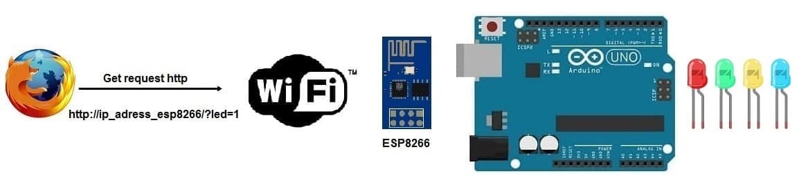 To light up four LEDs connected to an Arduino Uno board via Wi-Fi using the ESP8266 module and an HTTP GET request, you'll need to create a simple web server on the ESP8266 and send HTTP requests to it from a web browser or another device. Here's a step-by-step guide:
Hardware Setup:
1- Connect the four LEDs to four digital pins on the Arduino Uno (pin 4, pin5 and pin6).
2- Connect four resistors (e.g., 220-330 ohms) in series with the four LEDs.
3- Connect the ESP8266 module to the Arduino Uno using UART communication (TX and RX pins).
Software Setup:
1- Make sure you have the Arduino IDE installed on your computer.
2- Install the necessary libraries for the ESP8266 module. You can do this by going to "Tools" > "Manage Libraries" and searching for "ESP8266" or "Adafruit ESP8266."
Arduino Sketch (Code):
Create an Arduino sketch (code) that sets up the ESP8266 as a web server and controls the LED based on incoming HTTP GET requests:
|
1 2 3 4 5 6 7 8 9 10 11 12 13 14 15 16 17 18 19 20 21 22 23 24 25 26 27 28 29 30 31 32 33 34 35 36 37 38 39 40 41 42 43 44 45 46 47 48 49 50 51 52 53 54 55 56 57 58 59 60 61 62 63 64 65 66 67 68 69 70 71 72 73 74 75 76 77 78 79 80 81 82 83 84 85 86 87 88 89 90 91 92 93 94 95 96 97 98 99 100 101 102 103 104 |
#include <SoftwareSerial.h> SoftwareSerial esp8266(2,3); //Pin 2 & 3 of Arduino as RX and TX. Connect TX and RX of ESP8266 respectively. #define DEBUG true #define red_led_pin 4 //red LED is connected to Pin 4 of Arduino #define green_led_pin 5 //green LED is connected to Pin 5 of Arduino #define yellow_led_pin 6 //yellow LED is connected to Pin 6 of Arduino void setup() { pinMode(red_led_pin, OUTPUT); digitalWrite(red_led_pin, LOW); pinMode(green_led_pin, OUTPUT); digitalWrite(green_led_pin, LOW); pinMode(yellow_led_pin, OUTPUT); digitalWrite(yellow_led_pin, LOW); Serial.begin(9600); esp8266.begin(115200); //Baud rate for communicating with ESP8266. Your's might be different. esp8266Serial("AT+RST\r\n", 5000, DEBUG); // Reset the ESP8266 esp8266Serial("AT+CWMODE=1\r\n", 5000, DEBUG); //Set station mode Operation esp8266Serial("AT+CWJAP=\"HUAWEI Y5 2019\",\"b582058c4d86\"\r\n", 5000, DEBUG);//Enter your WiFi network's SSID and Password. while(!esp8266.find("OK")) { } esp8266Serial("AT+CIFSR\r\n", 5000, DEBUG);//You will get the IP Address of the ESP8266 from this command. esp8266Serial("AT+CIPMUX=1\r\n", 5000, DEBUG); esp8266Serial("AT+CIPSERVER=1,80\r\n", 5000, DEBUG); } void loop() { if (esp8266.available()) // Receive http request from web browser via wifi { if (esp8266.find("+IPD,")) { String msg; esp8266.find("?"); msg = esp8266.readStringUntil(' '); String command1 = msg.substring(0, 3); String command2 = msg.substring(4); if (DEBUG) { Serial.println(command1);//Must print "led" Serial.println(command2);//Must print "0","1","2", "3", "4" or "5" } delay(100); if (command2 == "0") { digitalWrite(red_led_pin, LOW); // Turn off the red LED } if (command2 == "1") { digitalWrite(red_led_pin, HIGH); // Turn on the red LED } if (command2 == "2") { digitalWrite(green_led_pin, LOW); // Turn off the green LED } if (command2 == "3") { digitalWrite(green_led_pin, HIGH); // Turn on the green LED } if (command2 == "4") { digitalWrite(yellow_led_pin, LOW); // Turn off the yellow LED } if (command2 == "5") { digitalWrite(yellow_led_pin, HIGH); // Turn on the yellow LED } if (command2 == "6") { digitalWrite(yellow_led_pin, LOW); // Turn off the blue LED } if (command2 == "7") { digitalWrite(yellow_led_pin, HIGH); // Turn on the blue LED } } } } String esp8266Serial(String command, const int timeout, boolean debug) { String response = ""; esp8266.print(command); long int time = millis(); while ( (time + timeout) > millis()) { while (esp8266.available()) { char c = esp8266.read(); response += c; } } if (debug) { Serial.print(response); } return response; } |
1- Replace "YourSSID" and "YourPassword" with your Wi-Fi network credentials.
2- Upload the sketch to your Arduino Uno.
Testing:
1- Open the Arduino IDE's Serial Monitor (Tools > Serial Monitor) to monitor the ESP8266's serial output. Ensure that the baud rate in the Serial Monitor matches the one set in your code (9600).
2- After the ESP8266 successfully connects to your Wi-Fi network, it will display an IP address in the Serial Monitor. Note this IP address; you will use it to send HTTP requests to the ESP8266.
3- Open a web browser or use a tool like "curl" to send HTTP GET requests to the ESP8266. For example:
To turn the red LED on: http://ESP8266_IP/?led=1
To turn the red LED off: http://ESP8266_IP/?led=0
To turn the green LED on: http://ESP8266_IP/?led=3
To turn the green LED off: http://ESP8266_IP/?led=2
To turn the yellow LED on: http://ESP8266_IP/?led=5
To turn the yellow LED off: http://ESP8266_IP/?led=4
To turn the blue LED on: http://ESP8266_IP/?led=7
To turn the blue LED off: http://ESP8266_IP/?led=6
Replace ESP8266_IP with the actual IP address displayed in the Serial Monitor.
Here is an example of the data displayed by the Arduino program in the serial monitor of the Arduino IDE:
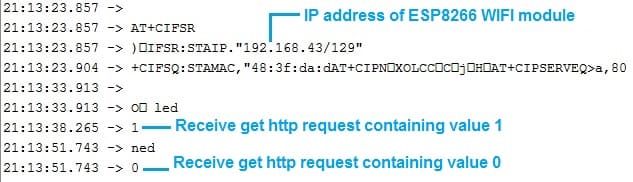
The four LEDs connected to your Arduino Uno should light up or turn off based on the HTTP GET requests you send. This demonstrates how to control an LED remotely via Wi-Fi using the ESP8266 module and HTTP requests.
The components needed to control four LEDs by the Arduino UNO board and ESP8266 module
To control four LEDs using an Arduino Uno and an ESP8266 module via Wi-Fi, you will need the following components:
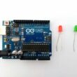
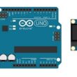
1- Arduino UNO board:
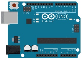
The Arduino UNO board is a popular microcontroller board based on the ATmega328P microcontroller. It is one of the most commonly used Arduino boards and provides a versatile platform for creating interactive electronic projects.
The Arduino UNO board is suitable for beginners and experienced users alike, offering a flexible and accessible platform for prototyping and building various electronic projects, from simple LED blinking to complex robotics and home automation systems.
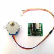
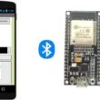
2- ESP8266 Wifi Module:
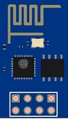
The ESP8266 is a low-cost and highly versatile Wi-Fi module developed by Espressif Systems. It has gained immense popularity in the maker and electronics communities due to its affordability, ease of use, and extensive capabilities. The module enables devices to connect to Wi-Fi networks and communicate over the internet, making it a fundamental building block for IoT (Internet of Things) projects.
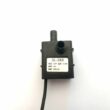
3V/5V power module
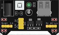
A "3V/5V power module" typically refers to a voltage regulator module or power supply module that can provide both 3.3V and 5V output voltages, allowing you to power various electronic components and devices that require different voltage levels. These modules are commonly used in electronics projects to ensure that different components receive the appropriate voltage.
3- Four LEDs (Light Emitting Diode):
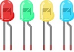
A Light Emitting Diode (LED) is a semiconductor device that emits light when an electric current passes through it. LEDs are widely used in various applications due to their efficiency, small size, and low power consumption.
4- Four resistros
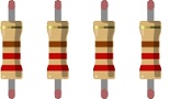
A resistor is a passive electronic component designed to introduce a specific amount of resistance into an electric circuit. Resistance is a measure of how much a material or component opposes the flow of electric current. Resistors are used for various purposes in electronic circuits, such as limiting current, dividing voltage, and providing voltage drops. They come in different shapes, sizes, and materials, and they are color-coded to indicate their resistance value.
5- Breadboard:

A breadboard is a useful tool for creating temporary electronic circuits. It allows you to connect components without soldering.
6- Jumper wires:

These wires are used to make connections between the Arduino UNO, ESP8266 module, LED, and breadboard.
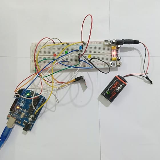
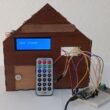
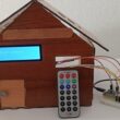
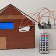
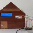
Mounting the Arduino UNO board with the ESP8266 Module and four LEDs
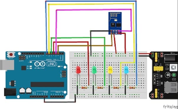
Here's a basic wiring diagram for connecting the LED to the Arduino Uno and ESP8266 module:
1- Connect the anode (longer lead) of the red LED to a current-limiting resistor (e.g., 220-330 ohms).
2- Connect the other end of the resistor to one of the Arduino Uno's digital output pins (pin 4).
3- Connect the cathode (shorter lead) of the red LED to the ground (GND) on the Arduino Uno.
4- Connect the anode (longer lead) of the green LED to a current-limiting resistor (e.g., 220-330 ohms).
5- Connect the other end of the resistor to one of the Arduino Uno's digital output pins (pin 5).
6- Connect the cathode (shorter lead) of the green LED to the ground (GND) on the Arduino Uno.
7- Connect the anode (longer lead) of the yellow LED to a current-limiting resistor (e.g., 220-330 ohms).
8- Connect the other end of the resistor to one of the Arduino Uno's digital output pins (pin 6).
9- Connect the cathode (shorter lead) of the yellow LED to the ground (GND) on the Arduino Uno.
10- Connect the anode (longer lead) of the blue LED to a current-limiting resistor (e.g., 220-330 ohms).
11- Connect the other end of the resistor to one of the Arduino Uno's digital output pins (pin 7).
12- Connect the cathode (shorter lead) of the blue LED to the ground (GND) on the Arduino Uno.
Additionally, for the ESP8266 module:
1- Connect the ESP8266's TX pin to the Arduino Uno's RX pin (pin 2).
2- Connect the ESP8266's RX pin to the Arduino Uno's TX pin (pin 3).
3- Connect the ESP8266's 3.3V pin to a 3.3V power source.
4- Connect the ESP8266's EN pin to a 3.3V power source.
5- Connect the ESP8266's GND pin to the ground (GND) on the power source.
Ensure that both the Arduino Uno and ESP8266 are properly powered and grounded.
0 comment
Leave a comment
Passion for robotics

Recent tutorials
Robotics workshop

Polpular tutorials


Making robots

Most commented tutorials
Robotic arm

Categories
Smart Home