Turn on an LED connected to the ESP32 board via WIFI
ESP32
07-09-23
1800
0
Tutorial plan
1- The difference between WIFI and Bluetooth
2- The ESP32 board and WIFI
3- The webserver with the ESP32 card
4- Lighting an LED connected to the ESP32 board via WIFI with Micropython
5- The components needed to use LED with the ESP32
6- Mounting the ESP32 with LED
The difference between WIFI and Bluetooth
Wi-Fi and Bluetooth are both wireless communication technologies, but they serve different purposes and have distinct characteristics. Here are the key differences between Wi-Fi and Bluetooth:
1- Purpose:
- Wi-Fi (Wireless Fidelity): Wi-Fi is primarily designed for high-speed data transmission over relatively long distances. It is commonly used for connecting devices to the internet, local area networks (LANs), and to each other for tasks like file sharing and media streaming.
2- Bluetooth: Bluetooth is designed for short-range wireless communication between devices. It is mainly used for connecting peripherals like keyboards, mice, headphones, speakers, and for transferring smaller files between devices such as smartphones, tablets, and laptops.
2- Range:
- Wi-Fi: Wi-Fi typically has a longer range compared to Bluetooth. Wi-Fi signals can cover large areas, depending on the router's power and the presence of obstacles.
- Bluetooth: Bluetooth has a shorter range, usually up to about 30 meters (100 feet). However, this range can vary depending on the Bluetooth version and the specific devices involved.
3- Data Transfer Rate:
- Wi-Fi: Wi-Fi offers much higher data transfer rates than Bluetooth. Modern Wi-Fi standards, like Wi-Fi 6 (802.11ax), can provide speeds of several gigabits per second, making it suitable for streaming high-definition video and fast internet access.
- Bluetooth: Bluetooth offers lower data transfer rates compared to Wi-Fi. The latest Bluetooth 5.x standard provides speeds of up to 2 Mbps, which is sufficient for most audio streaming and file transfers but not ideal for high-bandwidth tasks.
4- Power Consumption:
- Wi-Fi: Wi-Fi tends to consume more power, which is why devices like smartphones and laptops have limited battery life when actively using Wi-Fi connections.
- Bluetooth: Bluetooth is designed to be more power-efficient, making it suitable for battery-operated devices like wireless headphones and fitness trackers. Bluetooth Low Energy (BLE) is a variant of Bluetooth designed specifically for low-power applications.
5- Use Cases:
- Wi-Fi: Wi-Fi is commonly used for internet access, online gaming, streaming media, and connecting multiple devices to a network.
- Bluetooth: Bluetooth is often used for connecting accessories like headphones, speakers, keyboards, and mice to computers and mobile devices, as well as for tasks like transferring photos and files between smartphones.
In summary, Wi-Fi is better suited for high-speed, long-range wireless data transmission, while Bluetooth is designed for short-range connections between devices, emphasizing low power consumption and compatibility with various peripherals. The choice between Wi-Fi and Bluetooth depends on the specific use case and requirements of the devices involved.
The ESP32 board and WIFI
The ESP32 is a versatile microcontroller board that is well-known for its built-in Wi-Fi capabilities. Here's an overview of the ESP32 board and its Wi-Fi features:
1- ESP32 Microcontroller:
- The ESP32 is a microcontroller board based on the ESP32 chip, which is developed by Espressif Systems.
- It features a dual-core Xtensa LX6 CPU, which allows for multitasking and processing tasks efficiently.
- The ESP32 includes various built-in peripherals, including GPIO pins, ADCs, DACs, UART, SPI, I2C, and more, making it suitable for a wide range of IoT (Internet of Things) and embedded projects.
2- Wi-Fi Connectivity:
- One of the standout features of the ESP32 is its integrated Wi-Fi capabilities. It supports 2.4 GHz Wi-Fi 802.11 b/g/n, which enables it to connect to wireless networks and the internet.
- The Wi-Fi stack on the ESP32 allows it to act as both a station (client) that can connect to existing Wi-Fi networks and an access point (AP) that can create its own Wi-Fi network for other devices to connect to.
- The ESP32 supports secure Wi-Fi connections using protocols like WPA/WPA2 and even more advanced security features.
3- Applications:
The combination of the ESP32's processing power and built-in Wi-Fi makes it ideal for a wide range of applications, including:
- IoT devices: Sensors and actuators can be connected to the ESP32, which can then transmit data to the cloud or a local server via Wi-Fi.
- Home automation: ESP32 boards can be used to control smart home devices, monitor energy usage, and more.
- Wi-Fi-connected gadgets: You can build Wi-Fi-connected gadgets like weather stations, smart doorbells, and Wi-Fi-controlled robots.
- Internet-connected displays: ESP32 can be used to create web servers, IoT dashboards, and even simple web-based games.
4- Programming:
- The ESP32 can be programmed using various development environments, including the Arduino IDE, PlatformIO, and the Espressif IDF (IoT Development Framework).
- A rich ecosystem of libraries and resources is available for ESP32 development, making it easier to build Wi-Fi-enabled projects.
5- Power Consumption:
The ESP32 is relatively power-efficient, especially when compared to more power-hungry Wi-Fi modules. It offers power-saving features, making it suitable for battery-operated IoT devices.
In summary, the ESP32 board is a popular choice for IoT and embedded projects that require Wi-Fi connectivity. Its combination of a powerful microcontroller, integrated Wi-Fi capabilities, and extensive development support has made it a go-to platform for building a wide range of Wi-Fi-enabled devices and applications.
The webserver with the ESP32 card
Creating a web server using an ESP32 board and MicroPython is a popular project that allows you to control and monitor your ESP32 remotely through a web browser. Here are the general steps to set up a basic web server with an ESP32 and MicroPython:
1. Hardware Setup:
- Connect your ESP32 board to your computer via USB for programming and power.
- Ensure you have MicroPython firmware flashed onto your ESP32. You can use tools like esptool to flash the firmware.
2. Writing MicroPython Code:
- You can write and upload MicroPython code to your ESP32 using a tool like ampy or WebREPL.
- Below is a simple example code to create a basic web server with the ESP32 using MicroPython:
|
1 2 3 4 5 6 7 8 9 10 11 12 13 14 15 16 17 18 19 20 21 22 23 24 25 26 27 28 29 30 31 |
import network import machine import usocket as socket # Set up Wi-Fi ssid = "Your_SSID" password = "Your_Password" sta_if = network.WLAN(network.STA_IF) sta_if.active(True) sta_if.connect(ssid, password) # Create a socket s = socket.socket(socket.AF_INET, socket.SOCK_STREAM) s.bind(('', 80)) s.listen(5) def serve_webpage(client_socket): response = "HTTP/1.1 200 OK\r\nContent-Type: text/html\r\n\r\n" response += "<html><body>Hello, ESP32 Web Server!</body></html>" client_socket.send(response) client_socket.close() while True: try: client, addr = s.accept() print('Got a connection from %s' % str(addr)) serve_webpage(client) except KeyboardInterrupt: s.close() sta_if.disconnect() machine.reset() |
3. Replace Wi-Fi Credentials: Replace "Your_SSID" and "Your_Password" with your Wi-Fi network credentials.
4. Upload the Code: Use ampy or WebREPL to upload the MicroPython code to your ESP32.
5. Access the Web Server: Once the code is uploaded and running on your ESP32, it should create a web server. You can access the server by opening a web browser and entering the ESP32's IP address (you can find the IP address in your router's admin page) in the address bar.
6. Control and Monitor: You can customize the code to perform various actions or provide information via the web interface. This can include reading sensors, controlling actuators, or displaying real-time data.
This is a basic example of setting up a web server with an ESP32 and MicroPython. You can expand upon this by adding more HTML, CSS, JavaScript, and MicroPython code to create a more sophisticated web interface and control various aspects of your ESP32-based project.
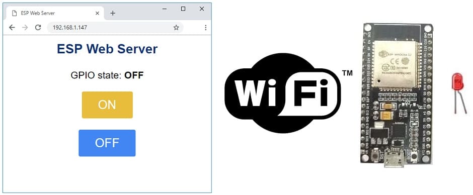
Lighting an LED connected to the ESP32 board via WIFI with Micropython
To light an LED connected to an ESP32 board via Wi-Fi using MicroPython and separate boot.py and main.py scripts, follow these steps:
1. Hardware Setup: Connect an LED to one of the GPIO pins on your ESP32. Make sure to connect the anode (longer leg) of the LED to a current-limiting resistor and then to the GPIO pin. Connect the cathode (shorter leg) of the LED to the ground (GND) pin.
2. Flash MicroPython: Ensure you have MicroPython firmware flashed onto your ESP32, and that it has Wi-Fi support enabled.
3. boot.py Script: Create a boot.py script (this script runs on boot and initializes Wi-Fi):
|
1 2 3 4 5 6 7 8 9 10 11 12 13 14 15 16 17 18 19 20 21 22 23 24 25 26 27 28 29 30 31 |
# Complete project details at https://RandomNerdTutorials.com try: import usocket as socket except: import socket from machine import Pin import network import esp esp.osdebug(None) import gc gc.collect() ssid = 'REPLACE_WITH_YOUR_SSID' password = 'REPLACE_WITH_YOUR_PASSWORD' station = network.WLAN(network.STA_IF) station.active(True) station.connect(ssid, password) while station.isconnected() == False: pass print('Connection successful') print(station.ifconfig()) led = Pin(23, Pin.OUT) |
4. main.py Script: Create a main.py script (this script will run after boot.py and control the LED):
|
1 2 3 4 5 6 7 8 9 10 11 12 13 14 15 16 17 18 19 20 21 22 23 24 25 26 27 28 29 30 31 32 33 34 35 36 37 38 39 40 41 |
# Complete project details at https://RandomNerdTutorials.com def web_page(): if led.value() == 1: gpio_state="ON" else: gpio_state="OFF" html = """<html><head> <title>ESP Web Server</title> <meta name="viewport" content="width=device-width, initial-scale=1"> <link rel="icon" href="data:,"> <style>html{font-family: Helvetica; display:inline-block; margin: 0px auto; text-align: center;} h1{color: #0F3376; padding: 2vh;}p{font-size: 1.5rem;}.button{display: inline-block; background-color: #e7bd3b; border: none; border-radius: 4px; color: white; padding: 16px 40px; text-decoration: none; font-size: 30px; margin: 2px; cursor: pointer;} .button2{background-color: #4286f4;}</style></head><body> <h1>ESP Web Server</h1> <p>GPIO state: <strong>""" + gpio_state + """</strong></p><p><a href="/?led=on"><button class="button">ON</button></a></p> <p><a href="/?led=off"><button class="button button2">OFF</button></a></p></body></html>""" return html s = socket.socket(socket.AF_INET, socket.SOCK_STREAM) s.bind(('', 80)) s.listen(5) while True: conn, addr = s.accept() print('Got a connection from %s' % str(addr)) request = conn.recv(1024) request = str(request) print('Content = %s' % request) led_on = request.find('/?led=on') led_off = request.find('/?led=off') if led_on == 6: print('LED ON') led.value(1) if led_off == 6: print('LED OFF') led.value(0) response = web_page() conn.send('HTTP/1.1 200 OK\n') conn.send('Content-Type: text/html\n') conn.send('Connection: close\n\n') conn.sendall(response) conn.close() |
5. Customize GPIO Pin: Replace LED_PIN with the GPIO pin number where your LED is connected. In the example, it's set to GPIO pin 23.
6. Upload Scripts: Upload both the boot.py and main.py scripts to your ESP32 using a tool like ampy or WebREPL.
7. Power On the ESP32: Power on your ESP32, and it should connect to your Wi-Fi network (as configured in boot.py) and start toggling the LED connected to the specified GPIO pin according to the logic in main.py.
This setup will automatically connect your ESP32 to Wi-Fi on boot and run the LED control code in main.py. Make sure to replace 'Your_WiFi_SSID' and 'Your_WiFi_Password' with your actual Wi-Fi credentials.
The components needed to control an LED by the ESP32 board
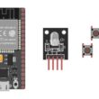
To control an LED with the ESP32 board, you will need the following components:
1- ESP32 Board:
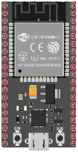
The ESP32 is a microcontroller board that features built-in WiFi and Bluetooth capabilities. It can be programmed and used to control the LED.
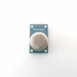
2- Resistor
![]()
A resistor is an essential electronic component used to impede or limit the flow of electric current in a circuit. It's designed to have a specific resistance value, which is measured in ohms (Ω). Resistors come in various shapes, sizes, and types to suit different applications.
3- LED (Light Emitting Diode):
![]()
A Light Emitting Diode (LED) is a semiconductor device that emits light when an electric current passes through it. LEDs are widely used in various applications due to their efficiency, small size, and low power consumption.
4- Breadboard:

A breadboard is a useful tool for creating temporary electronic circuits. It allows you to connect components without soldering.
5- Jumper wires:

These wires are used to make connections between the ESP32 board, LEDs, and breadboard.[/vc_column_text]
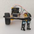
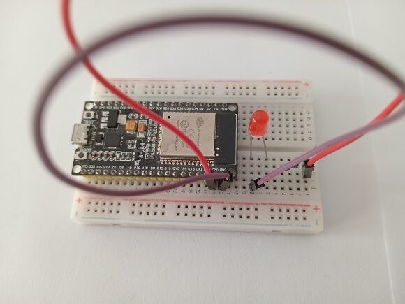
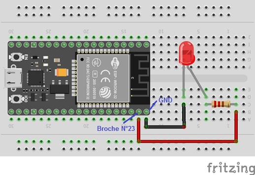
Mounting the ESP32 card with an LED
Once you have gathered these components, you can proceed with the following steps to control the LED:
1- Connect the anode of the LED (the longer leg) to a digital output pin on the ESP32 board. For example, you can connect it to GPIO pin 23.
2- Connect the cathode of the LED (the shorter leg) to the resistor. Then, connect the other end of the resistor to the ground (GND) pin on the ESP32 board.
0 comment
Leave a comment
Passion for robotics

Recent tutorials


Robotics workshop

Polpular tutorials


Making robots

Most commented tutorials


Robotic arm

Categories
Smart Home