Smart door access control using Micro:bit and RFID card
Tutorial plan
1- Introduction
2- Description of a Micro:bit-Powered Smart Door Access System Using RFID Cards
3- Required Components
4- Circuit Connections of system
5- Makecode program of system
Introduction
A Smart Door Access Control System using a magnetic card (commonly RFID-based) is a modern and secure way to control entry into buildings, rooms, or restricted areas. Instead of using traditional metal keys, users carry magnetic cards that store unique digital identifiers. When presented to a reader near the door, the system checks whether the card is authorized and either grants or denies access accordingly.
How It Works ?
1- A user places or swipes a magnetic (RFID) card near a card reader.
2- The reader scans the card’s unique ID.
3- A control system (such as a microcontroller, access control board, or embedded processor) compares the ID to a list of authorized users.
4- If the card is recognized:
- The system sends a signal to unlock the door (via an electric lock, servo, or motor).
- A message or sound confirms successful access.
5- If the card is not authorized:
- The system denies entry and may alert security or log the attempt.
Description of a Micro:bit-Powered Smart Door Access System Using RFID Cards
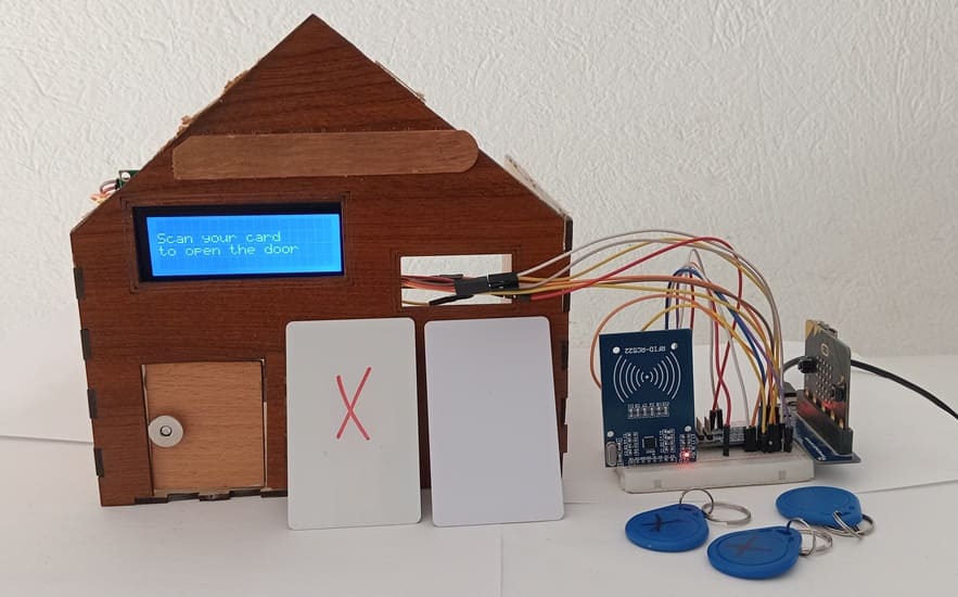
This project presents a smart door access control system built around the BBC Micro:bit microcontroller. The system is designed to enhance home or office security by allowing access only to authorized individuals carrying an RFID magnetic card.
At the heart of the project is the RFID-RC522 module, which reads the unique identifier (UID) of any RFID card brought close to it. The Micro:bit processes this UID and checks it against a list of authorized cards stored in the system. If the UID matches a registered card, the door unlocks by rotating a servomotor, simulating the action of opening a door.
To improve user interaction, an I2C LCD display is used to show real-time feedback such as:
“Scan your card”
“Card refused”
This visual feedback makes the system user-friendly and helps in debugging and demonstrations.
How It Works ?
1- When powered on, the LCD prompts the user to scan an RFID card.
2- The RFID-RC522 module detects the card and sends the UID to the Micro:bit.
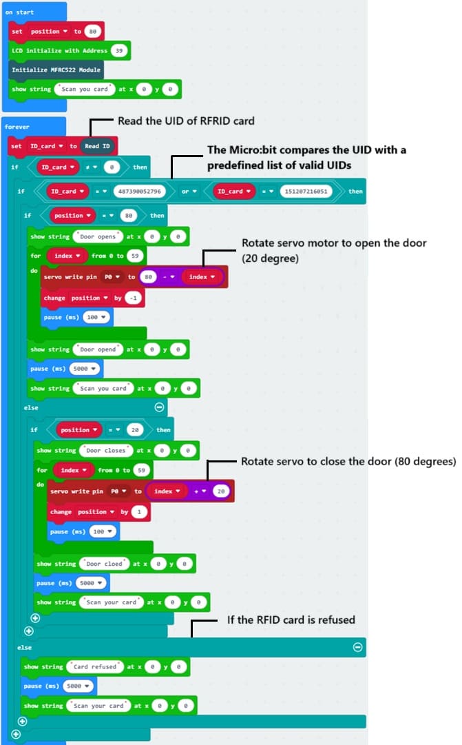
3- The Micro:bit compares the UID with a predefined list of valid UIDs.
4- If the UID matches, the Micro:bit:
- Displays "Door opens" on the LCD.
- Rotates the servomotor to unlock the door.
- The user approaches the RFID card to the RC522 reader again, the servomotor close the door.
5- If the UID does not match:
- "Card refused" is shown on the LCD.
- The door remains locked.
This system offers a simple yet effective way to secure entry points using affordable and easy-to-use components.
Required Components
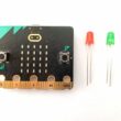
BBC Micro:bit
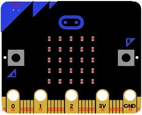
Function: Acts as the brain of the project. It processes input from the RFID module, controls the LCD and servomotor, and handles access logic.
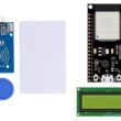
RFID-RC522 Module
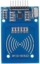
Function: Reads RFID cards or tags and sends their UID (Unique Identifier) to the Micro:bit.
RFID Cards or Tags

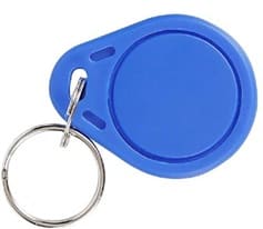
Function: Act as unique identifiers for individuals. Each has a unique UID stored in its memory.
I2C LCD Display (16x2 or 20x4)
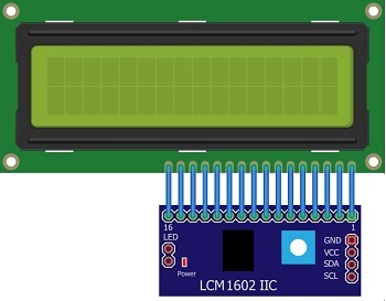
Function: Displays system status and user prompts such as “Scan your card,” “Access Granted,” or “Access Denied.”
Servomotor (e.g., SG90)

Function: Acts as the locking mechanism for the door. Rotates to open/close the door when access is granted.
GPIO Extension Card for Micro:bit
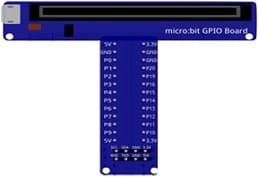
Function: Expands the number of usable input/output pins on the Micro:bit, making it easier to connect multiple components like the RFID reader, LCD, and servomotor.
Breadboard
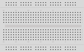
The breadboard is used for prototyping and connecting components without soldering.
It allows the easy insertion of wires and components for a flexible setup.
Jumper Wires

Jumper wires are used to make connections between components on the breadboard, Micro:bit, and GPIO extension card.
Wooden house prototype
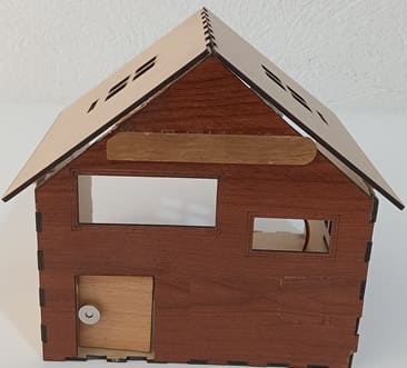
A miniature wooden house represents a real-world structure.
The door mechanism is attached to a servo motor, which rotates to open or close it.
The wooden prototype provides a stable frame for installing components like the IR sensor and LCD screen.
Circuit Connections of system
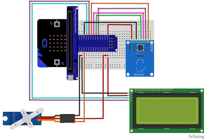
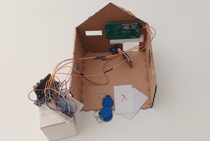
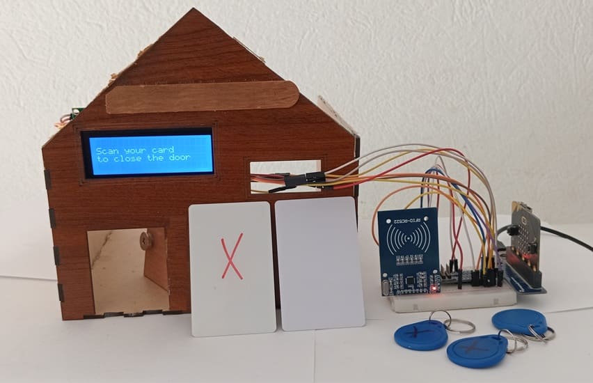
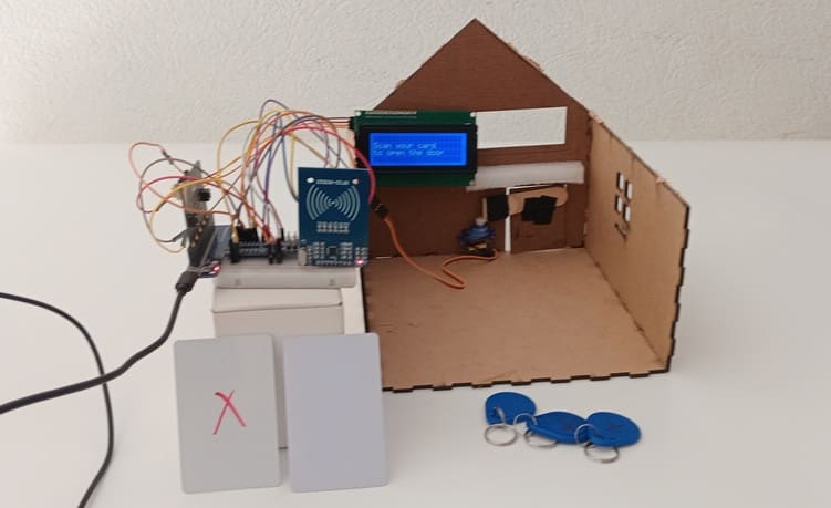
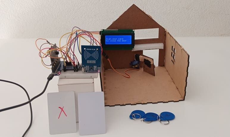
Connection of LCD I2C display to Micro:bit
LCD I2C Pin | Micro:bit Pin |
VCC | 5V |
GND | GND |
SDA | P20 |
SCL | P19 |
Connection of servo motor to Micro:bit
Servo motor Pin | Micro:bit Pin |
Brown wire (-) | GND pin |
Red wire (+) | 5V of GPIO card |
Yellow wire (Signal) | PO pin |
Connection of FRID-RC522 module to Micro:bit
RFID-RC522 module Pin | Micro:bit Pin |
VCC | 3V3 |
RST | P8 |
GND | GND |
MISO | P14 |
MOSI | P15 |
SCK | P13 |
SDA | P16 |
Makecode program of system
1- Open MakeCode (makecode.microbit.org).
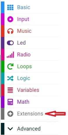
2- Click on Extensions.
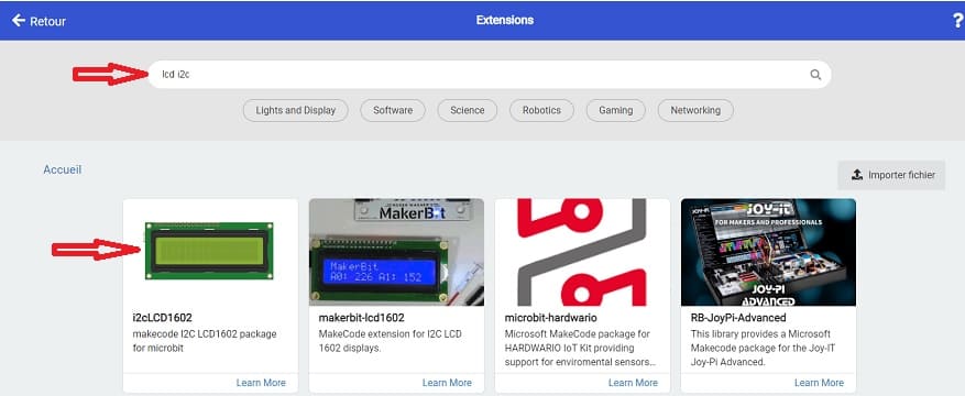
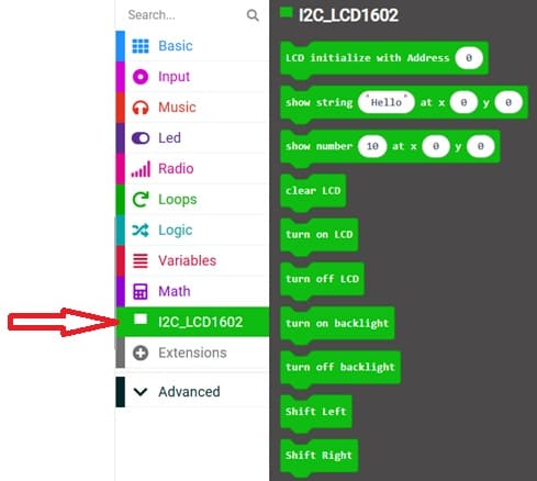
3- In the search bar, type "I2C LCD," and you should find an extension for the I2C LCD display. Add it to your project.
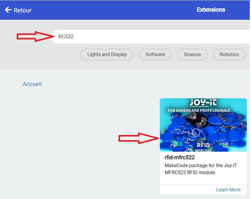
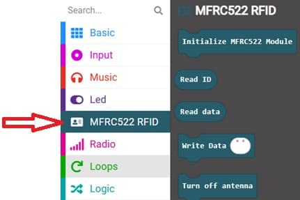
4- In the search bar, type "RC522," and you should find an extension for the RFID RC522 module (for reading RFID cards). Add it to your project.
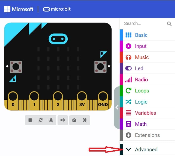
5- Go to advanced :
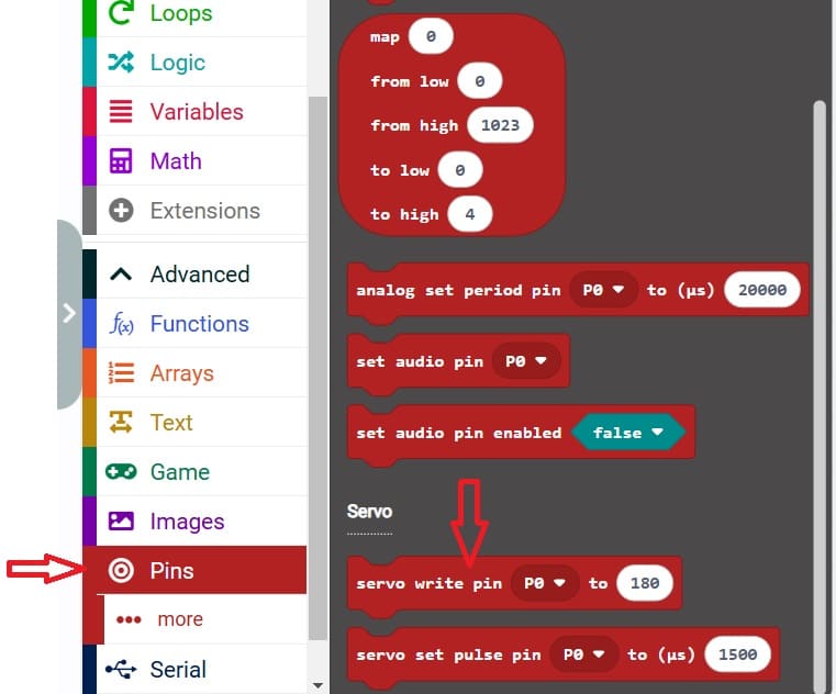
6- Go to Pin and choose 'servo write pinP0 to 180' instruction :
Here is a complete Makecode program with detailed comments for your Smart Door Access Control System
