Smart Arduino lighting system
Tutorial plan
1- How the smart Arduino lighting system works ?
2- Necessary system components
3- System connection diagram
4- Programming the Arduino UNO board
How the smart Arduino lighting system works ?
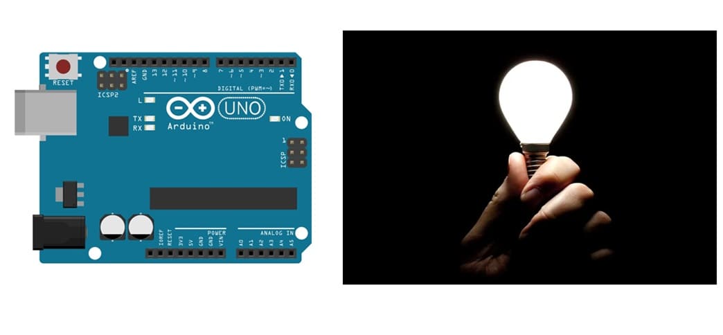
A smart Arduino lighting system that uses the KY-018 Photoresistor sensor and an LED works by adjusting the brightness or state of the LED based on the ambient light intensity. This system can automatically control the lighting in a room or environment, making it energy-efficient and convenient.
How It Works
1- Sensing Light Intensity
The KY-018 sensor outputs an analog voltage signal that corresponds to the light level in its environment.
In darkness: The resistance of the photoresistor is high, leading to a lower voltage signal.
In bright light: The resistance decreases, resulting in a higher voltage signal.
2- Processing the Signal
The Arduino reads the analog signal from the KY-018 sensor through one of its analog input pins (e.g., A0).
The analog signal is converted into a digital value ranging from 0 to 1023 (10-bit ADC resolution).
The Arduino processes this value to determine the current light level.
3. Controlling the LED
Based on the light level:
If the ambient light is low: The Arduino turns on the LED or increases its brightness.
If the ambient light is high: The Arduino dims the LED or turns it off to save energy.
Necessary system components
Arduino Board:
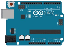
Acts as the microcontroller to process data and control the LED.
KY-018 Photoresistor Sensor:
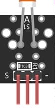
A light-dependent resistor (LDR) that changes its resistance based on the light intensity.
High resistance in darkness and low resistance in bright light.
LED:
![]()
Provides illumination, its brightness controlled by the Arduino.
Resistors:
![]()
Used to prevent damage to the LED and stabilize sensor readings.
Jumper Wires:
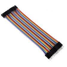
For making temporary connections and wiring between components.
Breadboard:
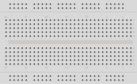
A breadboard is a useful tool for creating temporary electronic circuits. It allows you to connect components without soldering.
System connection diagram
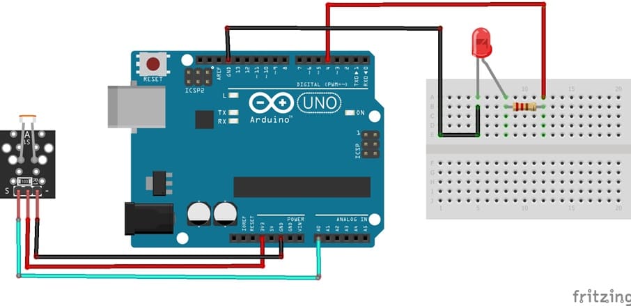
KY-018 Sensor:
- Connect DO pin of KY-018 sensor to A0 pin of Arduino
- Connect VCC pin of KY-018 sensor to 3.3V pin of Arduino
- Connect GND pin of KY-018 sensor to GND pin of Arduino
LED:
- Connect the anode (long leg) to digital pin (e.g., D4) via a current-limiting resistor (220Ω).
- Connect the cathode (short leg) to GND.
Programming the Arduino UNO board
The program for the automatic lighting system :
|
1 2 3 4 5 6 7 8 9 10 11 12 13 14 15 16 17 18 19 20 21 22 |
int digitalPin = 4; int analogPin = A0; // KY-026 analog interface int digitalVal; // digital readings int analogVal; //analog readings void setup() { pinMode(digitalPin, OUTPUT); digitalWrite(digitalPin, LOW); } void loop() { // read the value returned by the light sensor analogVal = analogRead(analogPin); if (analogVal>670){ // when the light sensor detects very low brightness digitalWrite(digitalPin, HIGH); // turn on red LED } else { digitalWrite(digitalPin, LOW); // turn off red LEDs } delay(100); } |

