Sending Data from Arduino to Smartphone using Matrix Keypad
Tutorial plan
1- What is a 4x4 matrix keyboard ?
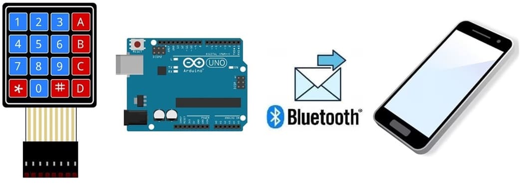
2- How Arduino send data from matrix keypad to Smartphone ?
3- Components Needed
4- Wiring the Components
5- Arduino program
6- Mobile application with MIT App Inventor
What is a 4x4 matrix keyboard ?
A 4x4 matrix keyboard is a type of input device commonly used in electronics projects and embedded systems to capture user input. It consists of 16 keys arranged in a 4-row by 4-column matrix, forming a grid. This matrix layout minimizes the number of microcontroller pins required to interface with the keypad, making it efficient and easy to use.
Working Principle
1. Scanning Process:
The microcontroller activates one row at a time by sending a signal (logic HIGH or LOW) to that row.
It then checks each column to see if a connection is made (i.e., if a key is pressed).
2. Key Press Detection:
When a key is pressed, the corresponding row and column are shorted.
The microcontroller identifies which row is active and which column is shorted, allowing it to determine the pressed key.
3. Matrix Encoding:
By mapping each row-column pair to a specific character, the microcontroller can interpret the key pressed.
How Arduino send data from matrix keypad to Smartphone ?
This project demonstrates how to send input from a 4x4 matrix keypad connected to an Arduino to a smartphone using the HC-06 Bluetooth module.
System Workflow
1. The user presses a key on the matrix keypad.
2. The Arduino detects which key is pressed and sends the corresponding data (e.g., number, letter, or symbol) to the HC-06 Bluetooth module.
3. The HC-06 Bluetooth module transmits the data wirelessly to the smartphone.
4. The smartphone app receives the data and displays it on the screen.
Components Needed
Arduino Uno :
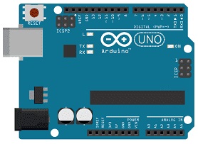
Processes the input from the matrix keypad and communicates with the HC-06 module.
4x4 Matrix Keypad:
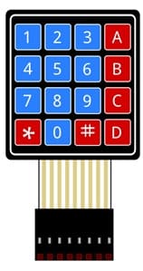
User input device for entering numbers, letters, or commands.
HC-06 Bluetooth Module:

Handles wireless communication between the Arduino and the smartphone.
Connecting Wires:
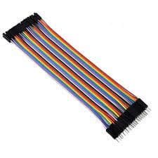
For connecting the keypad and HC-06 to the Arduino.
Smartphone:
Receives data via Bluetooth and displays it using an App Inventor app.
App Inventor:
Used to design and build the smartphone app for receiving data.
Wiring the Components
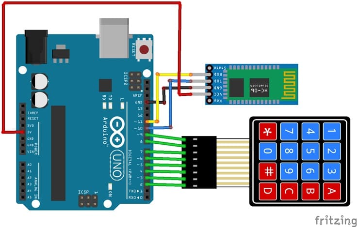
4x4 Matrix Keypad to Arduino:
We connect the 8 outputs of the keypad to the 8 pins of the ESP32 card following this order: D2, D3, D4, D5, D6, D7, D8 and D9.
HC-06 Bluetooth Module to Arduino:
VCC → Arduino 5V
GND → Arduino GND
TXD (Transmit) → Arduino RX (Pin 10)
RXD (Receive) → Arduino TX (Pin 11)
Arduino program
The following code reads input from the keypad and sends it to the smartphone via the HC-06 module.
We must install Keypad library.
|
1 2 3 4 5 6 7 8 9 10 11 12 13 14 15 16 17 18 19 20 21 22 23 24 25 26 27 |
#include <SoftwareSerial.h> #include <Keypad.h> const int ROW_NUM = 4; //four rows const int COLUMN_NUM = 4; //four columns char keys[ROW_NUM][COLUMN_NUM] = { {'1','2','3', 'A'}, {'4','5','6', 'B'}, {'7','8','9', 'C'}, {'*','0','#', 'D'} }; byte pin_rows[ROW_NUM] = {9, 8, 7, 6}; //connect to the row pinouts of the keypad byte pin_column[COLUMN_NUM] = {5, 4, 3, 2}; //connect to the column pinouts of the keypad Keypad keypad = Keypad( makeKeymap(keys), pin_rows, pin_column, ROW_NUM, COLUMN_NUM ); SoftwareSerial hc06(10,11); void setup(){ hc06.begin(9600); } void loop(){ char key = keypad.getKey(); if(key) //We press a key on the keyboard { hc06.print(key); //Send message to smartphone delay(100); } } |
Mobile application with MIT App Inventor
Designing the Interface
1- Open MIT App Inventor (appinventor.mit.edu).
2- Create a new project and design the app interface with:
A ListPicker for Bluetooth device selection.
A Label to display the received key data.
A BluetoothClient component for communication.
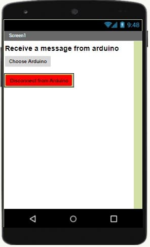
3- Setting Up the Blocks
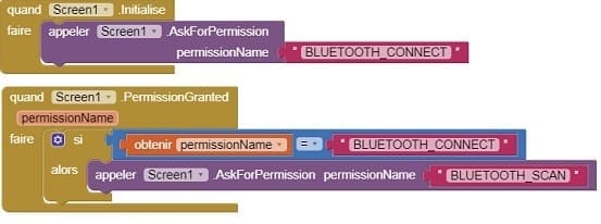
a) Starting with Android 12, Bluetooth permissions have been enhanced to improve security and user data protection. This is why we must declare the authorizations that your application needs in the AndroidManifest.xml file. For Bluetooth, you'll need to include ACCESS_FINE_LOCATION, BLUETOOTH_SCAN, and possibly BLUETOOTH_CONNECT permissions, depending on the features you're using.
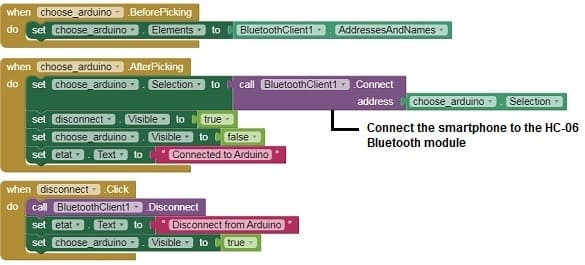
b) Add the the necessary blocks to connect the smartphone to the HC-06 Bluetooth module
c) Receive and Display Data:
Use the BluetoothClient.ReceiveText block to continuously read data sent from the Arduino.
Display the received data in the Label.

Download project aiaDownload application
Testing the System
1-Connect the Arduino to your computer and upload the code.
2- Ensure the HC-06 is connected and powered properly. The LED on the HC-06 should blink, indicating it's ready for pairing.
3- Pair the HC-06 with your smartphone via Bluetooth settings.
4- Launch the App Inventor app, connect to the HC-06 using the ListPicker, and wait for the connection.
5- Press keys on the matrix keypad and observe the data appearing on the smartphone app.

