RFID based access control system with ESP32 card
Tutorial plan
1- What is an access control system ?
2- Presentation of RFID based access control system by ESP32
3- Required Components
4- Circuit Connections of system
5- Micropython program to control our system
What is an access control system ?
An Access Control System (ACS) is a security mechanism that regulates who or what can view, enter, or use resources within a system, building, or network. It ensures that only authorized individuals or devices can access specific areas or data while preventing unauthorized access.
Types of Access Control Systems
1- Physical Access Control – Restricts access to physical locations such as buildings, rooms, or secure areas using:
- Key cards or RFID badges
- PIN codes or passwords
- Biometrics (fingerprint, facial recognition, etc.)
- Mobile apps or NFC technology
2- Logical Access Control – Manages access to digital systems, networks, and data using:
- User authentication (passwords, two-factor authentication)
- Role-based access control (RBAC)
- Encryption and security policies
Components of an Access Control System
- Authentication Devices – RFID readers, keypads, biometric scanners
- Control Panel – Processes access requests and grants or denies access
- Locks & Barriers – Electronic locks, turnstiles, or gates
- Access Control Software – Manages user permissions and logs access events
- User Database – Stores authorized user credentials
Benefits of an Access Control System
- Enhanced security and reduced risk of unauthorized access
- Improved tracking and monitoring of entry and exit
- Convenient and flexible access management
- Integration with security cameras and alarms for better surveillance
Presentation of RFID based access control system by ESP32
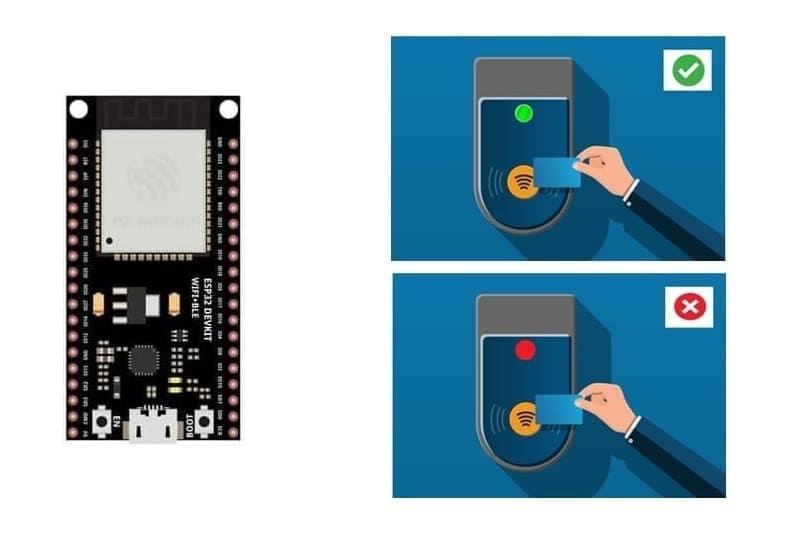
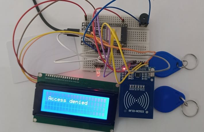
This project demonstrates an RFID-based access control system using an ESP32 microcontroller. The system reads RFID cards or badges, verifies access permissions, and provides feedback through an LCD I2C display, a buzzer, and an RGB LED module. This type of system is commonly used in offices, schools, and secure areas to restrict unauthorized access.
1- The RFID-RC522 module continuously scans for RFID cards/badges.
2- When a card is placed near the reader, the ESP32 retrieves the Unique Identifier (UID) of the card.
3- The ESP32 compares the UID with a predefined list of authorized users stored in the code or EEPROM.
4- Based on the verification result:
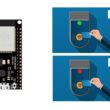
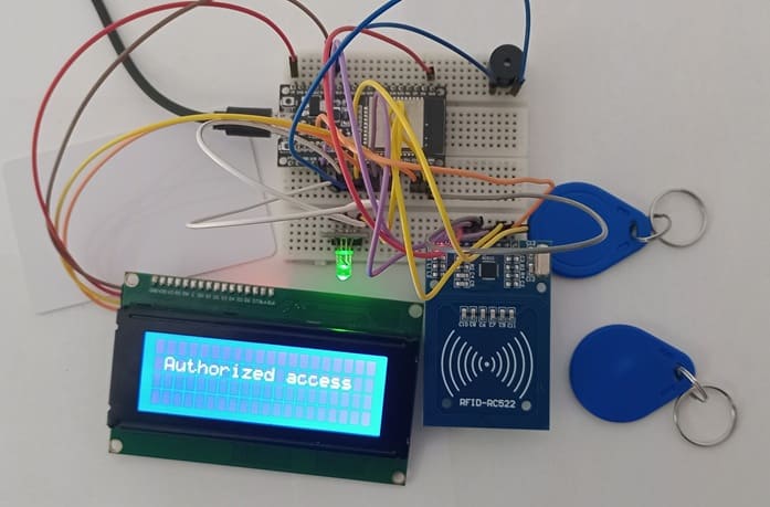
a) If authorized, the system displays "Access Granted", turns the RGB LED green.
b) If unauthorized, the system displays "Access Denied", turns the RGB LED red, and activates the buzzer (long beep).
Required Components
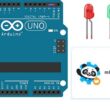
ESP32 Microcontroller
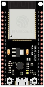
The ESP32 is the main controller of the system, responsible for reading the RFID card data, verifying access permissions, and controlling outputs such as the LCD display, buzzer, and RGB LED.
It supports multiple GPIO pins, making it suitable for interfacing with different modules like the RFID-RC522, LCD, buzzer, and LED.
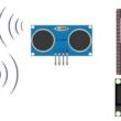
RFID RC-522 Module
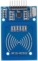
The RFID-RC522 module is responsible for reading RFID cards and tags using radio frequency identification (RFID).
It operates at 13.56 MHz and supports reading and writing to RFID cards.
The module communicates with the ESP32 via SPI protocol.
When a card is scanned, the module retrieves the Unique Identifier (UID) and sends it to the ESP32 for processing.
RFID Card/Badge

![]()
The RFID card or badge is used as an authentication key.
Each card has a unique ID (UID) stored in its memory.
The RFID-RC522 module reads this UID when the card is brought close to it.
If the UID matches a predefined list of authorized users, access is granted.
LCD I2C Display (16x2 or 20x4)

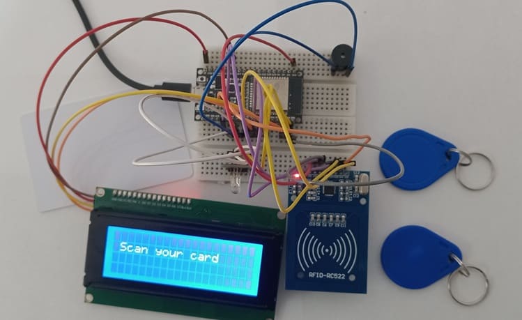
The LCD display provides real-time feedback to the user.
It shows messages such as “Scan Your Card”, “Access Granted”, or “Access Denied”.
The I2C interface reduces the number of required pins, making it easier to connect to the ESP32.
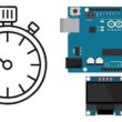
Buzzer
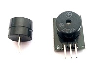
The buzzer provides audio feedback based on access status.
It produces a long beep when access is denied.
RGB LED Module
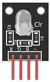
The RGB LED module provides visual feedback:
- Green LED: Access granted
- Red LED: Access denied
Circuit Connections of system
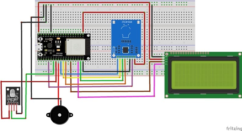
Connection of RFID-RC522 module
RFID-RC522 Pin | ESP32 Pi |
VCC | 3V3 |
RST | GPIO 2 |
GND | GND |
MISO | GPIO 19 |
MOSI | GPIO 23 |
SCK | GPIO 18 |
SDA (SS) | GPIO 5 |
Connection of I2C LCD display
LCD I2C Pin | ESP32 pin |
VCC | 5 volt |
GND | GND |
SDA | GPIO 21 |
SCL | GPIO 22 |
Connection of Buzzer
Buzzer pin | ESP32 pin |
(+) pin | GPIO 17 |
(-) pin | GND |
Connection of RGB LED module
LED RGB pin | ESP32 pin |
Red pin | GPIO 16 |
Green pin | GPIO 4 |
GND pin | GND pin |
Micropython program to control our system
Before running the code, install the necessary libraries:
- MFRC522 (for RFID module)
- i2c_lcd and lcd_api for I2C LCD screen
|
1 2 3 4 5 6 7 8 9 10 11 12 13 14 15 16 17 18 19 20 21 22 23 24 25 26 27 28 29 30 31 32 33 34 35 36 37 38 39 40 41 42 43 44 45 46 47 48 49 50 51 52 53 54 55 56 57 58 59 60 61 62 63 64 |
from time import sleep_ms from machine import Pin, SPI, SoftI2C,ADC from mfrc522 import MFRC522 from lcd_api import LcdApi from i2c_lcd import I2cLcd sck = Pin(18, Pin.OUT) mosi = Pin(23, Pin.OUT) miso = Pin(19, Pin.OUT) sda = Pin(5, Pin.OUT) I2C_ADDR = 0x27 totalRows = 4 totalColumns = 20 # RFID setup spi = SPI(baudrate=100000, polarity=0, phase=0, sck=sck, mosi=mosi, miso=miso) # I2C setup for LCD (Adjust 0x27 or 0x3F based on your module) i2c = SoftI2C(scl=Pin(22), sda=Pin(21), freq=10000) #initializing the I2C method for ESP32 lcd = I2cLcd(i2c, I2C_ADDR, totalRows, totalColumns) # Initialize components buzzer=Pin (17,Pin.OUT) red_pin=Pin (16,Pin.OUT) green_pin=Pin (4,Pin.OUT) def do_read(): while True: rdr = MFRC522(spi, sda) uid = "" # the ESP32 retrieves the Unique Identifier (UID) of the card (stat, tag_type) = rdr.request(rdr.REQIDL) if stat == rdr.OK: (stat, raw_uid) = rdr.anticoll() if stat == rdr.OK: uid = ("0x%02x%02x%02x%02x" % (raw_uid[0], raw_uid[1], raw_uid[2], raw_uid[3])) print(uid) lcd.clear() lcd.move_to(1,1) # The ESP32 compares the UID with the UID stored in the code if uid=="0xdb1bb201" : lcd.putstr("Authorized access") green_pin.value(1) # turns the RGB LED green else: lcd.putstr("Access denied") buzzer.value(1) # activates the buzzer red_pin.value(1) # turns the RGB LED red sleep_ms(5000) # after 5s, desactivate LED RGB and the Buzzer red_pin.value(0) green_pin.value(0) buzzer.value(0) lcd.clear() lcd.move_to(1,1) lcd.putstr('Scan your card') else: dui="" lcd.clear() lcd.move_to(1,1) lcd.putstr('Scan your card') do_read() |
Explanation of the Code
1- Initializing Components
The ESP32 SPI pins are configured for the RFID-RC522 module.
The I2C communication is set up for the LCD display.
The Buzzer and RGB LED are initialized for feedback.
2- Scanning for RFID Cards
The program continuously scans for RFID badges.
When a card is detected, it extracts the UID and converts it into a string.
3- Checking Authorization
If the UID matches the predefined list, access is granted.
Otherwise, access is denied.
4- Providing Feedback
The LCD screen displays messages like “Authorized access” or “Access Denied”.
The RGB LED turns Green (granted) or Red (denied).
The buzzer beeps differently for each outcome.
0 comment
Leave a comment
Passion for robotics

Recent tutorials


Robotics workshop

Polpular tutorials


Making robots

Most commented tutorials


Robotic arm

Categories
Smart Home