RFID based access control system with Arduino
Tutorial plan
1- What is an access control system ?
2- Presentation of RFID based access control system with Arduino
3- Required Components
4- Circuit Connections
5- Arduino program to control our system
What is an access control system ?
An Access Control System (ACS) is a security solution that regulates who or what can view, use, or access resources in a computing environment or physical location. It is a fundamental component of security frameworks, ensuring that only authorized individuals, devices, or systems can access specific areas, data, or services.
Types of Access Control Systems
1- Physical Access Control Systems:
Restrict entry to buildings, rooms, or secure areas.
Examples: Keycards, biometric scanners (fingerprint, facial recognition), PIN pads, and turnstiles.
2- Logical Access Control Systems:
Restrict access to computer systems, networks, or data.
Examples: Passwords, multi-factor authentication (MFA), role-based access control (RBAC), and encryption.
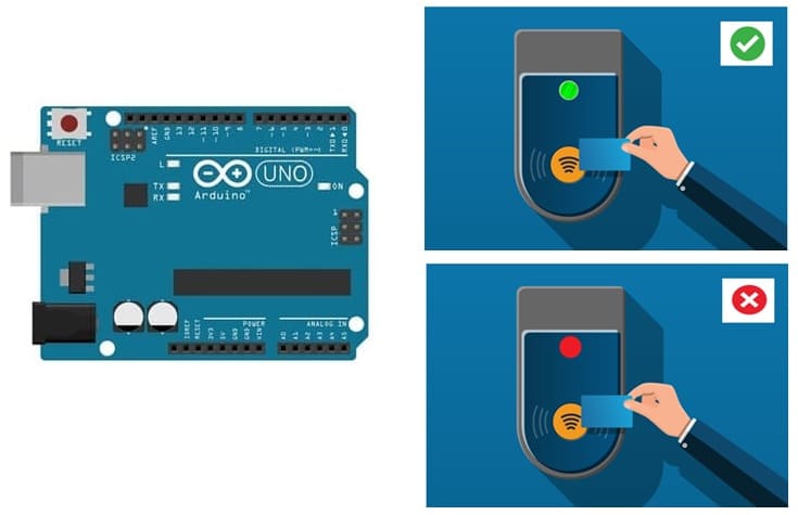
Presentation of RFID based access control system with Arduino
This project uses an Arduino, an RFID-RC522 module, an LCD I2C display, a buzzer, and an RGB LED module to create a secure access control system. Authorized users can gain access when they scan an RFID card, while unauthorized users will be denied.
Working Principle
1- User scans an RFID card on the RFID-RC522 module.
2- The Arduino reads the unique ID (UID) of the card.
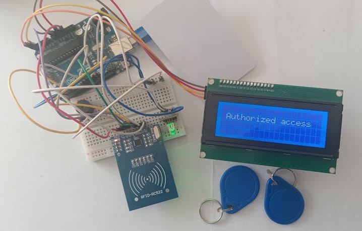
3- If the UID matches a pre-authorized list, access is granted:
- LCD displays "Authorized Access "
- RGB LED turns Green
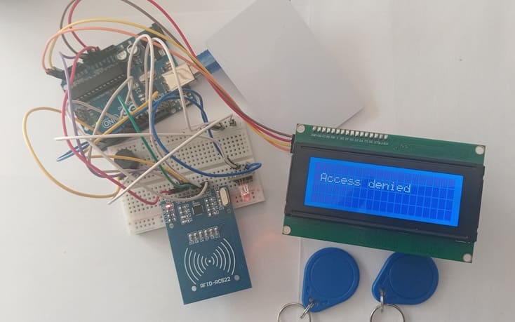
4- If the UID is not recognized, access is denied:
- LCD displays "Access Denied"
- RGB LED turns Red
- Buzzer emits an alert sound
Required Components
Arduino UNO (Microcontroller)
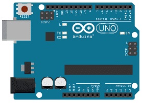
The Arduino UNO is the main processing unit of the system. It reads the RFID card’s unique identifier (UID), compares it to a stored list, and controls the output devices (LCD, buzzer, and RGB LED).
Role in System:
- Communicates with the RFID-RC522 module via SPI
- Sends messages to the LCD I2C display via I2C
- Controls the buzzer and RGB LED for feedback
- (Optional) Activates a relay module to unlock a door
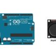
RFID-RC522 Module (RFID Reader)
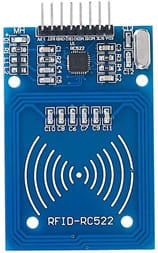
The RFID-RC522 is a 13.56 MHz RFID reader used to scan RFID tags and retrieve their unique identifier (UID).
Role in System
- Detects RFID cards or key fobs
- Extracts UID from RFID tags
- Sends UID data to Arduino via SPI
RFID Cards / Key Fobs

![]()
RFID cards and key fobs are passive devices that contain a pre-programmed unique identifier (UID). When placed near the RFID-RC522 module, they communicate via electromagnetic induction.
Role in System
- Acts as the user’s access credential
- Contains a UID that the Arduino checks for authentication
LCD I2C Display (16x2 or 20x4)

The LCD I2C display is used to show system messages like "Access Granted" or "Access Denied". The I2C interface allows simpler wiring with only two data lines.
Role in System
Displays real-time messages to the user
Reduces the need for external serial monitors
Buzzer (Audio Feedback)
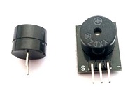
A small piezo buzzer provides audio feedback when a card is scanned.
Role in System
Long beep when access is denied
RGB LED Module (Visual Feedback)
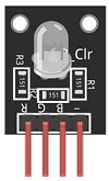
The RGB LED module consists of three LEDs (Red, Green, Blue) that light up in different colors based on access status.
Role in System
Green LED ON → Access granted
Red LED ON → Access denied
Circuit Connections
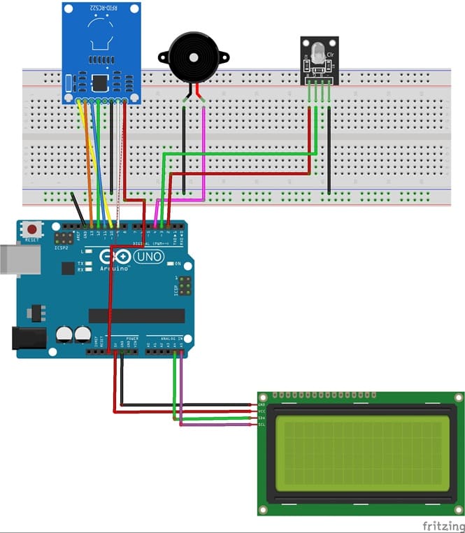
Connection RFID-RC522 to Arduino
RFID-RC522 | Arduino UNO | Description |
VCC | 3.3V | Power supply |
GND | GND | Ground |
SDA (SS) | Pin 10 | Slave Select (SS) |
SCK | Pin 13 | SPI Clock (SCK) |
MOSI | Pin 11 | Master Out Slave In (MOSI) |
MISO | Pin 12 | Master In Slave Out (MISO) |
RST | Pin 9 | Reset |
Connection LCD I2C display to Arduino
LCD I2C Display Pin | Arduino Pin |
GND | GND |
VCC | 5V |
SDA | A4 |
SCL | A5 |
Connection Buzzer to Arduino
Buzzer pin | Arduino pin |
(-) pin | GND |
(+) pin | D4 |
Connection RGB LED module to Arduino
LED RGB pin | Arduino pin |
Red pin | D2 |
Green pin | D3 |
GND | GND |
Arduino program to control our system
Here is the Arduino program for an RFID-based access control system using an Arduino UNO, an RFID-RC522 module, an LCD I2C display, a buzzer, and an RGB LED module. This program reads an RFID card, checks if it is authorized, and provides visual (LCD, RGB LED) and audio (buzzer) feedback.
This code uses the MFRC522 library for RFID communication and the LiquidCrystal_I2C library for the LCD display.
1- Open Arduino IDE.
2- Go to Sketch → Include Library → Manage Libraries.
3- Search for MFRC522 and install it.
4- Search for LiquidCrystal_I2C and install it
|
1 2 3 4 5 6 7 8 9 10 11 12 13 14 15 16 17 18 19 20 21 22 23 24 25 26 27 28 29 30 31 32 33 34 35 36 37 38 39 40 41 42 43 44 45 46 47 48 49 50 51 52 53 54 55 56 57 58 59 60 61 62 63 64 65 66 67 68 69 70 71 72 73 74 75 76 77 78 79 80 81 82 83 84 85 |
#include <LiquidCrystal_I2C.h> #include <SPI.h> #include <MFRC522.h> // RFID module pins #define SS_PIN 10 #define RST_PIN 9 // Initialize LCD (40x4) with I2C address 0x27 LiquidCrystal_I2C lcd(0x27, 40, 4); MFRC522 rfid(SS_PIN, RST_PIN); const int PinRed = 2; // for Red color of RGB LED const int PinGreen = 3; // for Green color of RGB LED const int buzzerPin = 4; // for bool cardDetected = false; // Track card status void setup() { Serial.begin(9600); lcd.init(); lcd.backlight(); SPI.begin(); rfid.PCD_Init(); lcd.setCursor(1, 1); lcd.print("Scan your card"); pinMode(buzzerPin, OUTPUT); pinMode(PinRed, OUTPUT); pinMode(PinGreen, OUTPUT); digitalWrite(PinRed, LOW); // Eteindre la couleur rouge du LEDRGB digitalWrite(PinGreen, LOW); // Eteindre la couleur rouge du LEDRGB } void loop() { if (!rfid.PICC_IsNewCardPresent() || !rfid.PICC_ReadCardSerial()) { if (cardDetected) { // Only update LCD if the message changes lcd.clear(); lcd.setCursor(1, 1); lcd.print("Scan your card"); cardDetected = false; // Reset status } return; } cardDetected = true; // Read and display UID String uid = ""; for (byte i = 0; i < rfid.uid.size; i++) { Serial.print(rfid.uid.uidByte[i], HEX); uid += String(rfid.uid.uidByte[i], HEX); if (i < rfid.uid.size - 1) { uid += ":"; } } lcd.clear(); lcd.setCursor(1, 1); if (uid=="a9:f0:e8:b8") { // If the UID matches a pre-authorized list lcd.print("Authorized access"); // Green LED ON digitalWrite(PinGreen, HIGH); } else { // If the UID is not recognized lcd.print("Access denied"); // warning beep with Buzzer digitalWrite(buzzerPin, HIGH); // // Red LED ON digitalWrite(PinRed, HIGH); } delay(5000); // Stop the Buzzer digitalWrite(buzzerPin, LOW); // Red LED OFF, Green LED OFF digitalWrite(PinRed, LOW); digitalWrite(PinGreen, LOW); rfid.PICC_HaltA(); rfid.PCD_StopCrypto1(); } |
0 comment
Leave a comment
Passion for robotics

Recent tutorials


Robotics workshop

Polpular tutorials


Making robots

Most commented tutorials


Robotic arm

Categories
Smart Home