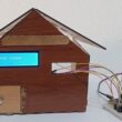
Remotely light up two lamps by remote control using Micro:bit

Tutorial plan
1- Introducing the KY-032 Infrared Sensor
2- The components needed to use the KY-032 infrared sensor and two lamps with the Micro:bit board
3- Mounting the Micro:bit board with the KY-032 infrared sensor and two lamps
4- Makecode programming of the Micro:bit board to receive data from the KY-032 infrared sensor and light up two lamps
Introducing the KY-032 Infrared Sensor
The KY-032 Infrared Sensor is a module that is commonly used in electronics and robotics projects for detecting the presence of infrared signals. It is also known as an infrared obstacle avoidance sensor module. The module consists of an infrared emitter (LED) and an infrared receiver (phototransistor) placed side by side.
When using the KY-032 Infrared Sensor, it's important to keep in mind that it primarily detects the presence of objects based on their reflective properties rather than their distance. The effectiveness of the sensor can be affected by factors such as ambient light and the reflective properties of the objects being detected.
To receive an infrared signal from a remote control using the KY-032 sensor with a Micro:bit board, you'll need to follow these steps:
1- Connect the KY-032 sensor to the Micro:bit board. The KY-032 module typically has three pins: VCC (power), GND (ground), and OUT (output). Connect the VCC pin to a 3.3V pin on the Micro:bit, the GND pin to a ground pin, and the OUT pin to any digital input pin on the Micro:bit.
2- Import the necessary libraries. In your Micro:bit programming environment (such as MakeCode or MicroPython), import the libraries required for infrared communication. For MakeCode, you can use the "infrared" extension, which provides blocks for working with infrared signals. For MicroPython, you may need to install additional libraries specific to the KY-032 module.
3- Configure the Micro:bit to receive infrared signals. Use the appropriate programming blocks or functions to set up the Micro:bit to receive infrared signals. In MakeCode, you can drag and drop the "on infrared received" block and define the actions to be performed when an infrared signal is received. In MicroPython, you'll need to write code to initialize the infrared sensor and define an event handler for handling received signals.
4- Program the Micro:bit to interpret the received signal. Depending on your project's requirements, you'll need to decode and interpret the received infrared signal from the remote control. This typically involves checking the specific codes transmitted by the remote control for different buttons or actions and responding accordingly.
5- Test and iterate. Upload the program to the Micro:bit and test it by pressing buttons on the remote control. Monitor the output on the Micro:bit to ensure that it correctly receives and interprets the infrared signals from the remote control. If needed, make adjustments to the program or the sensor's sensitivity to improve performance.
The components needed to use the KY-032 infrared sensor and two lamps with the Micro:bit board
To use the KY-032 infrared sensor and two lamps with the Micro:bit board, you will need a few components and connections. Here's a list of the required items:
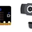
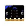
Micro:bit board:

The Micro:bit board is a small, programmable microcontroller board designed for education and beginner-friendly coding projects. It was developed by the BBC, in collaboration with various partners, as a tool to introduce young people to programming and electronics.
KY-032 Infrared Sensor:
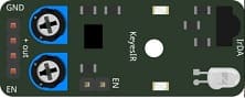
This sensor detects infrared signals and can be used to detect objects or receive signals from a remote control.
Two Relays Module:
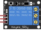
The relay plays a crucial role in controlling high-power or high-voltage devices like lamps using a microcontroller such as the Micro:bit. The Micro:bit, being a low-power device, cannot directly control these high-power devices due to differences in voltage and current requirements.
The relay acts as a switch that is controlled by the Micro:bit. When the Micro:bit sends a signal (typically a digital signal) to the relay module, the relay switches its internal contacts, allowing or interrupting the flow of electricity to the lamp.
Two lamps (220V):

The lamp you want to control, which is rated for 220V. Ensure it's in working condition and safe to use.
Power Supply for the Lamp:

You'll need a power source for the lamp, typically a 220V AC power supply.
Wiring:
Various wires and cables for connecting the components in your circuit.
Breadboard:

A breadboard is a useful tool for creating temporary electronic circuits. It allows you to connect components without soldering.
Jumper wires:

These wires are used to make connections between the Micro:bit, KY-032 sensor, relays, lamps, and breadboard.
The GPIO expansion card for the Micro:bit card

The GPIO expansion board for the Micro:bit board expands the capabilities of the Micro:bit board by adding more input/output (GPIO) pins and additional functionality.
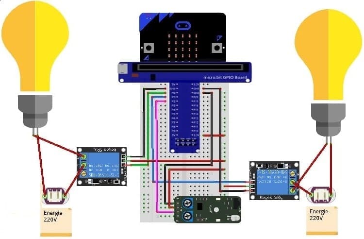
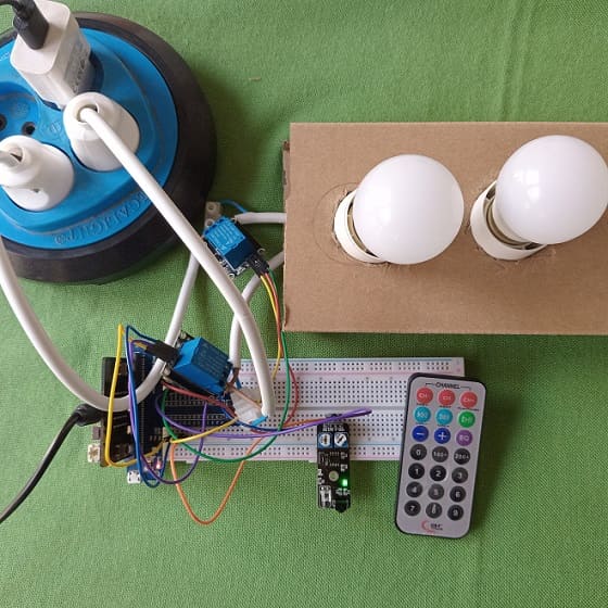
Mounting the Micro:bit board with the KY-032 infrared sensor and two lamps
To mount the Micro:bit board with the KY-032 infrared sensor and two lamps, you will need a breadboard and some jumper wires. Here are the steps to connect them:
1- Place the Micro:bit board on the breadboard, ensuring that the edge connector is aligned with the breadboard's power rails.
2- Connect the GND (ground) pin of the Micro:bit board to the negative (-) rail of the breadboard using a jumper wire.
3-Connect theKY-032 infrared sensor to the Micro:bit
- Insert the KY-032 infrared sensor into the breadboard. Make sure the sensor's pins are aligned with different rows on the breadboard.
- Connect the VCC pin of the KY-032 sensor to the 3.3V pin of the Micro:bit board using a jumper wire.
- Connect the GND pin of the KY-032 sensor to the GND pin of the Micro:bit board using a jumper wire.
- Connect the OUT pin of the KY-032 sensor to one of the pin P2 on the Micro:bit board using a jumper wire.
4- Connect the first Relay to the Micro:bit:
- Connect the relay's control pin (S) to pin P0 of Micro:bit board
- Connect the pin (+) of relay to pin 3.3V of Micro:bit board.
- Connect the relay's ground pin (GND) to the Micro:bit's GND.
5- Connect the first Lamp and the power supply to the Relay:
- Connect one of the lamp's wires to the normally open (NO) terminal of the relay.
- Connect the phase wire of the power supply to the relay's common (COM) terminal.
- Connect the neutral wire of the power supply directly to the neutral wire of the lamp.
5- Connect the second Relay to the Micro:bit:
- Connect the relay's control pin (S) to pin P1 of Micro:bit board
- Connect the pin (+) of relay to pin 3.3V of Micro:bit board.
- Connect the relay's ground pin (GND) to the Micro:bit's GND.
6- Connect the second Lamp and the power supply to the Relay:
- Connect one of the lamp's wires to the normally open (NO) terminal of the relay.
- Connect the phase wire of the power supply to the relay's common (COM) terminal.
- Connect the neutral wire of the power supply directly to the neutral wire of the lamp.
Makecode programming of the Micro:bit board to receive data from the KY-032 infrared sensor and light up two lamps
To program the Micro:bit board using Microsoft MakeCode to receive data from the KY-032 infrared sensor and light up two lamps based on the received data, you can follow these steps:
1- Open the MakeCode editor for Micro:bit at https://makecode.microbit.org/.
2- Start a new project or open an existing one.
3- Add the necessary packages for the infrared sensor. Click on the "Advanced" category in the toolbox on the left, and then click on "Extensions". 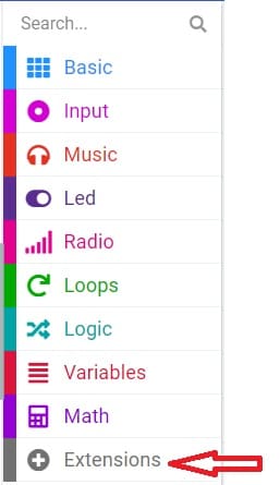
4- In the search bar, type "https://github.com/osoyoo/OSOYOO_IR_V3/" and click on the "OSYOO-IR-Silvery-Receiver" extension to import it into your project. 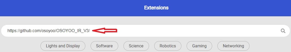
5- Initialize the KY-032 infrared sensor:
Insert a "on start" block from the "Basic" category to initialize the program when the Micro:bit board starts. 
Insert the "connect IR receiver at pin P0 and decode OSOYOO" block from the "OSYOO_SilveryIR_V3" category to initialize the KY-032 sensor. Specify the pin to which the sensor is connected (for example, P2).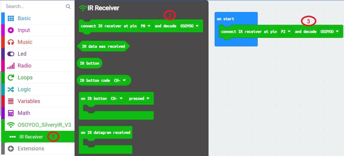
6- Add an event handler for receiving infrared signals :
Insert an "on IR Button" block from the "OSYOO_SilveryIR_V3" category to trigger an action when the infrared signal is received and specify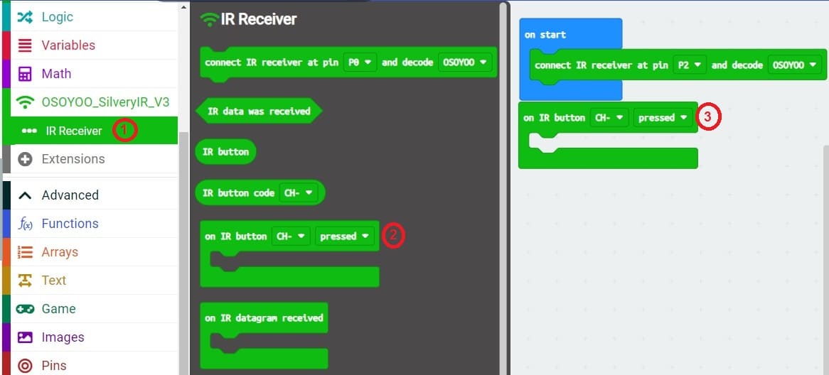 button on the remote control.
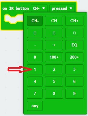
7- Insert a block "digital write pin P0 to 0" inside the block "on IR button 1 pressed".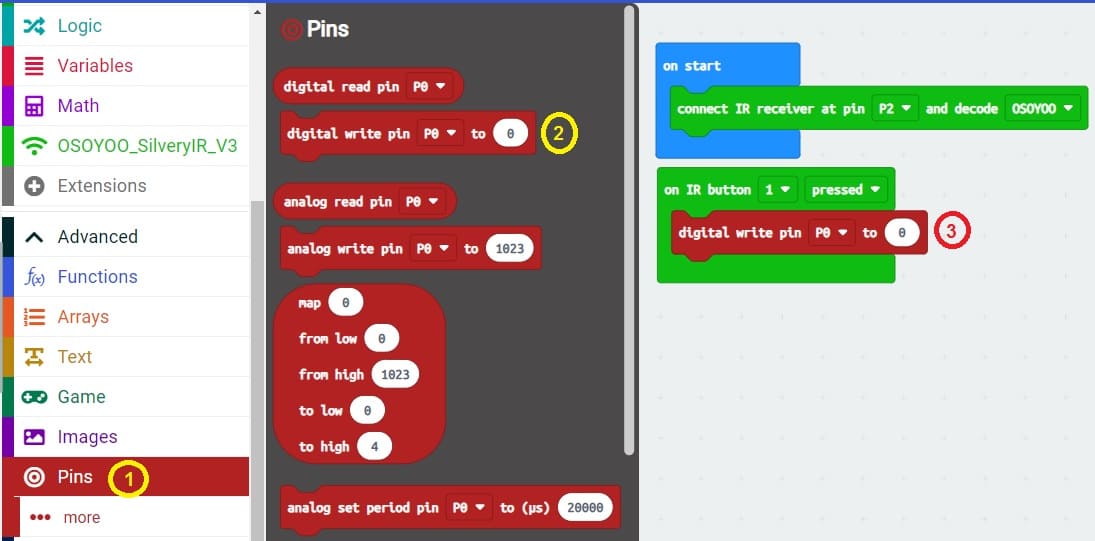
8- Set the state of the block "digital write pin P0 to 0" to "1" to turn on the first relay connected to the first lamp by pressing the 1 key on the remote control.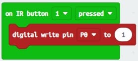
9- repeat steps 6, 7, 8 and 9 to turn off the second relay by pressing button 2 on the remote control.
10- Insert a block "digital write pin P1 to 0" inside the block "on IR button 1 pressed" to turn off the second relay connected to the second lamp by pressing key 1 of the remote control.
11- Insert a block "digital write pin P1 to 0" inside the block "on IR button 2 pressed" and change the value 0 to 1 to turn on the second relay connected to the second lamp by pressing the 2 button on the remote control.
11- Upload the program to your Micro:bit board by connecting it to your computer via a USB cable and clicking the "Upload" button in the MakeCode editor.
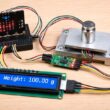
Here is the complete program which allows to turn on and off two lamps by a remote control :
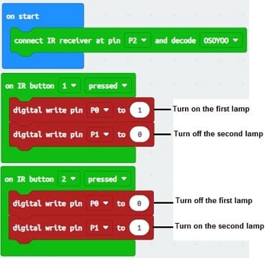
Now, when you press the selected button on your infrared remote control in front of the KY-032 sensor, the lamp connected to relay will light up. Make sure you understand the pinout and specifications of your KY-032 sensor for proper use with the Micro:bit board.
0 comment
Leave a comment
Passion for robotics

Recent tutorials


Robotics workshop

Polpular tutorials


Making robots

Most commented tutorials


Robotic arm

Categories
Smart Home