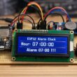
Open a door using Micro:bit and remote control
Tutorial plan
1- Remotely control the opening of a door
2- Remotely Controlling the Opening with Micro:bit
3- Required Components
4- Circuit Connections of system
5- Makecode program to control the door by Micro:bit
Remotely control the opening of a door
Remotely controlling the opening of a door using a remote control refers to the ability to unlock or open a door wirelessly using a handheld transmitter device. The remote sends signals to a receiver connected to a door-opening mechanism, such as a servo motor, solenoid lock, or relay-controlled motor.
This system is widely used in home automation, garage doors, electronic gates, smart locks, and secure access control systems.
To implement a remote-controlled door-opening system, the following components are required:
1- Remote Control (Transmitter)
Sends a signal when a button is pressed.
Can use infrared (IR), radio frequency (RF), Bluetooth, Wi-Fi, or Zigbee.
Example: Car key fob, TV remote, RF keychain remote.
2- Receiver Module
Installed near the door.
Receives the signal from the remote and processes it.
Example: IR receiver module (VS1838B), RF receiver (433MHz MX-05V), Bluetooth module (HC-05), Wi-Fi module (ESP32/ESP8266).
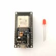
3- Microcontroller (if needed for processing signals)
Processes the received signal and activates the motor or lock.
Example: Arduino, ESP32, ESP8266, Micro:bit.
4- Door Opening Mechanism
Servo Motor – Rotates a latch or handle.
Electromagnetic Lock (Solenoid) – Unlocks the door.
Relay-Controlled Motor – Drives an electric motor to open the door.
Remotely Controlling the Opening with Micro:bit
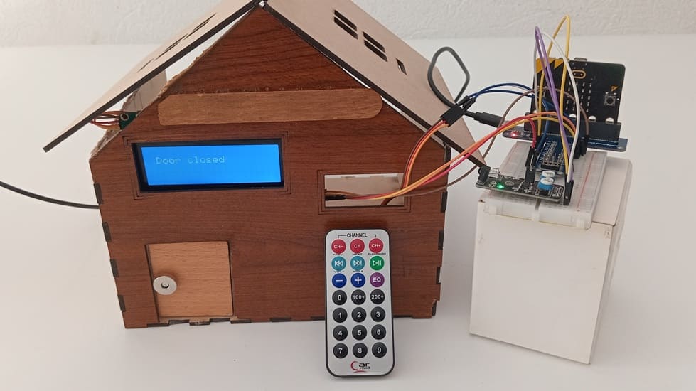
This system enables remote control of a door using an infrared (IR) remote control, a Micro:bit, an HY-032 IR sensor, a servo motor, and an LCD I2C screen. When the user presses a button on the IR remote, the HY-032 sensor detects the signal and sends it to the Micro:bit, which then processes the command to either open or close the door by controlling the servo motor. The LCD I2C screen provides real-time feedback on the door status.
Step-by-Step Functioning of the System
Step 1: User Presses a Button on the Remote Control
The user presses the "0" or "1" on the IR remote.
The remote emits an infrared signal with a specific unique code.
Step 2: IR Signal is Detected by HY-032 Sensor
The HY-032 sensor detects the infrared (IR) signal and converts it into a digital signal.
This signal is sent to the Micro:bit’s input pin (e.g., Pin P1).
Step 3: Micro:bit Processes the Signal
The Micro:bit reads the received IR code and compares it with pre-programmed values.
If the code matches a predefined command:
a) If it corresponds to "Open", it triggers the servo to rotate to 20°.
b) If it corresponds to "Close", it triggers the servo to rotate back to 80°.
The Micro:bit also updates the LCD I2C screen to show the current door status.
Step 4: Servo Motor Moves to Open or Close the Door
The Micro:bit sends PWM signals to the servo motor connected to Pin P0.
The servo motor rotates:
20° to Open the door.
80° to Close the door.
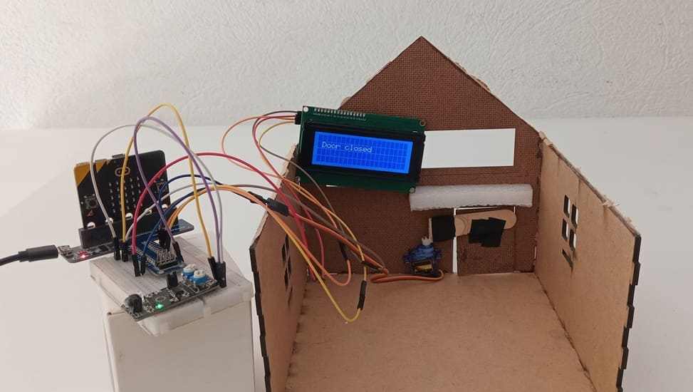
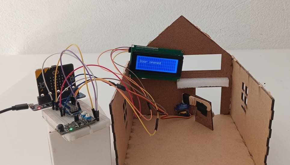
Step 5: LCD I2C Screen Displays Door Status
LCD screen updates to indicate the door’s status.
Required Components
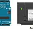
Micro:bit (Main Controller)

The Micro:bit is a small microcontroller board that processes inputs from the IR sensor and controls the servo motor.
It receives signals from the KY-032 IR receiver, determines whether to open or close the door, and sends the appropriate PWM signal to the servo.
The Micro:bit also communicates with the LCD I2C screen via I2C protocol to display messages.
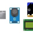
HY-032 Infrared (IR) Receiver Module
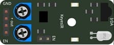
The KY-032 IR receiver detects infrared signals from a remote control and sends the corresponding digital signal to the Micro:bit.
It consists of a photodiode and an amplifier circuit to filter and decode the IR signals.
Infrared (IR) Remote Control
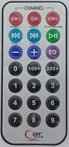
The IR remote control sends infrared signals when a button is pressed.
Each button has a unique encoded signal, which the HY-032 sensor detects and sends to the Micro:bit.
Servo Motor
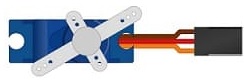
The servo motor is responsible for the physical movement of the door.
It rotates between 0° and 90° to either lock or unlock the door.
The Micro:bit controls the servo using Pulse Width Modulation (PWM) signals.
LCD I2C Screen (16x2 or 20x4)
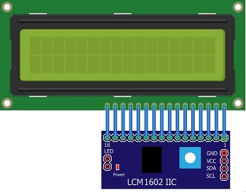
The LCD I2C screen displays real-time status updates, such as "Door Open" or "Door Closed".
It communicates with the Micro:bit using I2C protocol (SDA & SCL pins).
GPIO Extension Card for Micro:bit

The GPIO (General Purpose Input/Output) expansion board makes it easier to connect multiple components to the Micro:bit.
It provides additional pins and breakout headers for connecting servo motors, sensors, and an LCD screen.
Breadboard

The breadboard is used for prototyping and connecting components without soldering.
It allows the easy insertion of wires and components for a flexible setup.
Jumper Wires
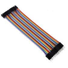
Jumper wires are used to make connections between components on the breadboard, Micro:bit, and GPIO extension card.
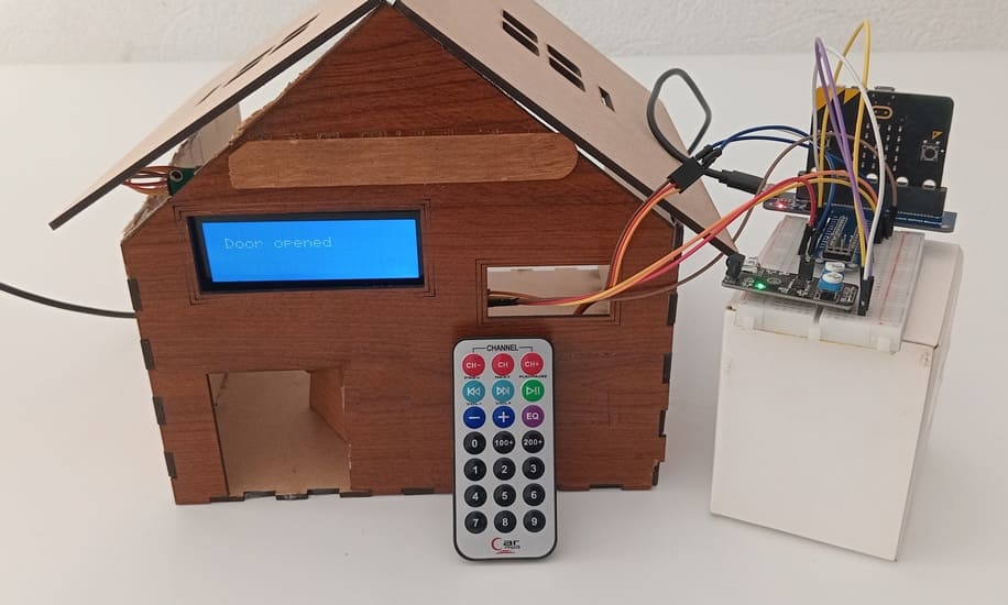
Wooden house prototype
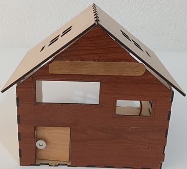
A miniature wooden house represents a real-world structure.
The door mechanism is attached to a servo motor, which rotates to open or close it.
The wooden prototype provides a stable frame for installing components like the IR sensor and LCD screen.
Circuit Connections of system
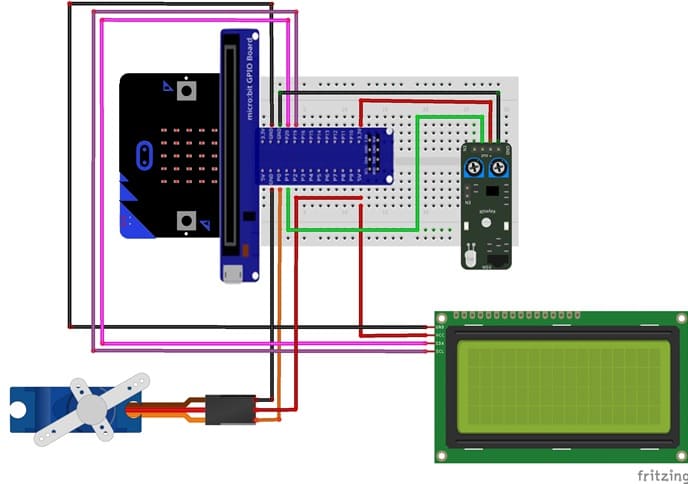
Connection of LCD I2C display to Micro:bit
LCD I2C Pin | Micro:bit Pin |
VCC | 5V |
GND | GND |
SDA | P20 |
SCL | P19 |
Connection of servo motor to Micro:bit
Servo motor Pin | Micro:bit Pin |
Brown wire (-) | GND pin |
Red wire (+) | 5V of GPIO card |
Yellow wire (Signal) | PO pin |
Connection of KY-032 sensor to Micro:bit
KY-032 pin | Micro:bit pin |
GND | GND |
VCC | 3V3 |
OUT | P1 |
Makecode program to control the door by Micro:bit
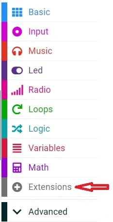
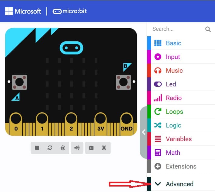
1- Open MakeCode (makecode.microbit.org).
2- Click on Extensions.
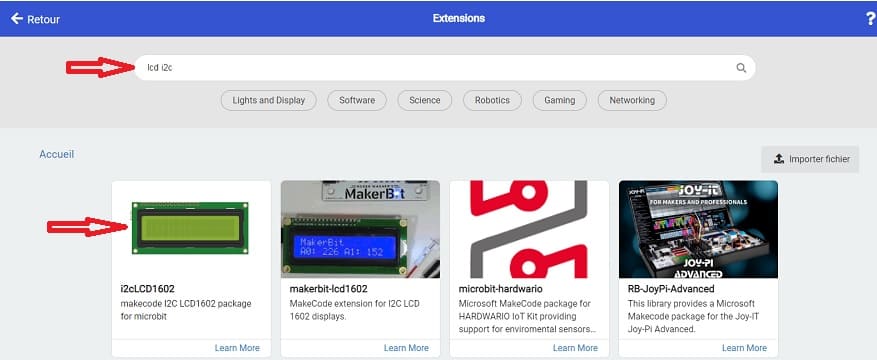
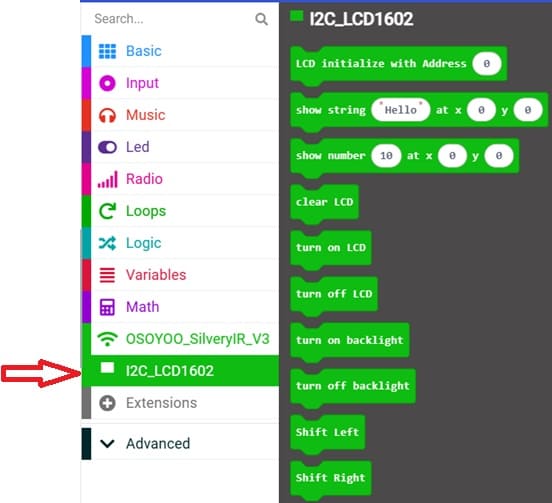
3- In the search bar, type "I2C LCD," and you should find an extension for the I2C LCD display. Add it to your project.
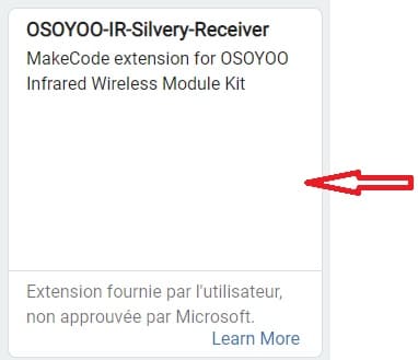
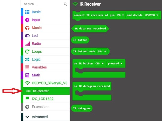
4- In the search bar, type "https://github.com/osoyoo/OSOYOO_IR_V3/" and click on the "OSYOO-IR-Silvery-Receiver" extension to import it into your project in order to use the KY-032 sensor.
5- Go to advanced :
6- Go to Pin and choose 'servo write pinP0 to 180' instruction :

Below is a MakeCode program to remotely control a door using a Micro:bit, a servo motor, an I2C LCD display, and a KY-032 sensor.
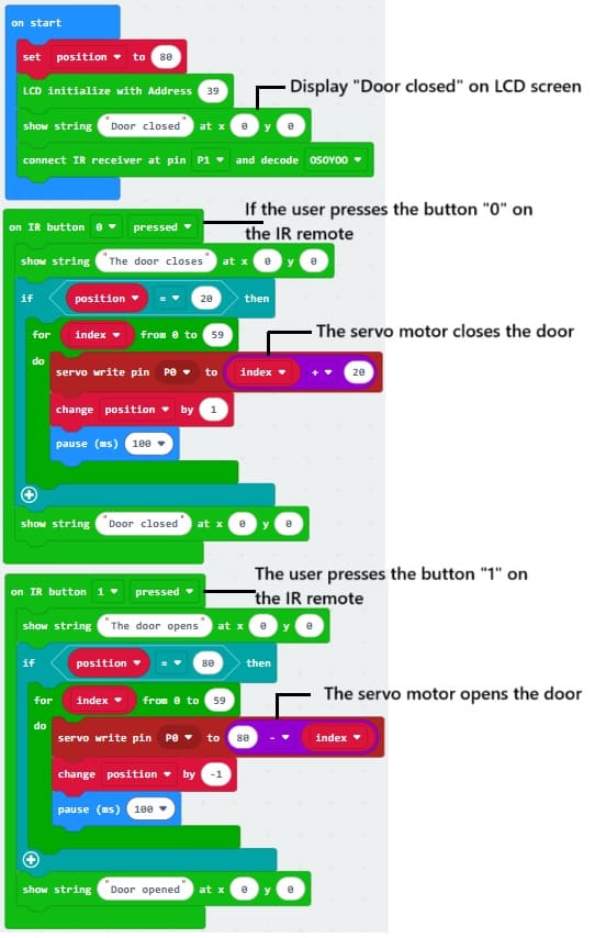
This MakeCode project allows remote and automatic control of a door using a Micro:bit, servo motor, KY-032 sensor, and an I2C LCD display.
1- Initialize LCD Display
2- Listen for Remote Signal
3- Control Servo and Display Door Status
0 comment
Leave a comment
Passion for robotics

Recent tutorials


Robotics workshop

Polpular tutorials


Making robots

Most commented tutorials


Robotic arm

Categories
Smart Home