Remote-Controlled Door System with ESP8266 NodeMCU
Tutorial plan
1- Remotely control the opening of a door
2- Remotely Controlling the door with ESP8266 NodeMCU
3- Required Components
4- Circuit Connections of system
5- Micropython program to control the system
Remotely control the opening of a door
Remotely controlling the opening of a door refers to the process of enabling the door's locking and/or physical opening mechanism to be operated from a distance using an electronic system. This control is achieved through the transmission of signals—wired or wireless—from a user interface or control device to an actuator mechanism attached to the door.
Core Components Involved
User Interface (Input Device):
A remote control, smartphone app, keypad, RFID reader, computer interface, or any device that sends a command to open the door.
Communication Medium:
The pathway through which the signal is transmitted. This can include:
Wireless (e.g., Wi-Fi, Bluetooth, GSM, RF, IR)
Wired (e.g., Ethernet, serial communication)
Control Unit (Processing System):
A microcontroller or embedded system (e.g., Arduino, ESP32, Raspberry Pi) that receives the command, processes it, and triggers the actuator.
Actuator (Output Mechanism):
A mechanical or electromechanical device such as a:
Servo motor rotates the lock or handle
Solenoid lock engages or releases a bolt
Linear actuator physically moves the door
Relay-controlled motor drives automated opening systems
Feedback:
Sensors or indicators (e.g., magnetic contact sensor, IR sensor, LCD screen) to provide status updates (door open, closed, locked, etc.).
Purpose and Advantages
Convenience: Open or close a door without being physically present.
Security: Restrict access to authorized users via authentication methods (e.g., RFID cards, passwords).
Automation: Integrate into smart home or building systems.
Accessibility: Assist people with limited mobility.
Example Use Cases
Smart home entrance systems
Remote-controlled garage doors
Hotel room access with NFC cards
Office doors with facial recognition systems
Automated gates with RF remotes
Remotely Controlling the door with ESP8266 NodeMCU
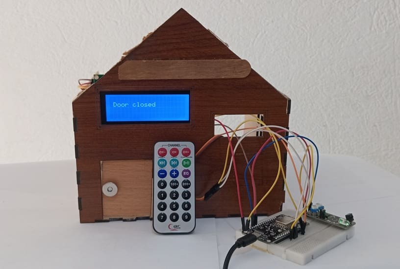
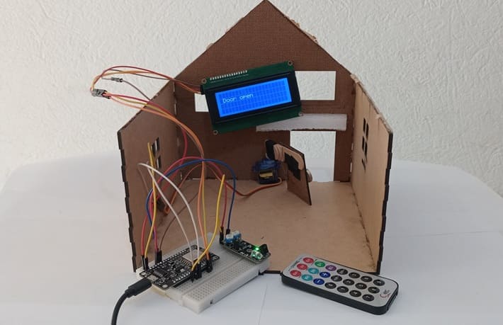
To design and implement a door control system that allows the user to open and close a door remotely using an infrared (IR) remote control. The system utilizes an ESP8266 NodeMCU to interpret the IR signal received via a KY-032 IR sensor, controls a servo motor for the door mechanism, and provides real-time status feedback using an LCD I2C display.
System Overview:
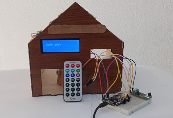
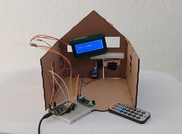
This system provides a simple, secure, and wireless method of controlling door access. The user interacts with the door system by pressing a button on an IR remote control. The IR signal is received by the KY-032 sensor, decoded by the ESP8266 NodeMCU, and based on the signal, the servo motor rotates to either open or close the door. An I2C LCD display shows the current status of the door (e.g., "Door Open", "Door Closed").
Working Principle:
Signal Reception:
The user presses a button on the IR remote.
The KY-032 sensor receives the IR signal and outputs a digital signal.
Signal Processing:
The ESP8266 reads the digital signal from the KY-032.
Each button on the remote corresponds to a unique code (e.g., 0xFFA25D).
The ESP8266 matches the received code to a predefined command (e.g., open/close).
Actuation:
If the received code corresponds to “open,” the servo motor rotates to pull the door open (e.g., 20°).
If the code corresponds to “close,” the servo rotates back to its original position (e.g., 90°).
Display Feedback:
The LCD shows a message like "Door Opened" or "Door Closed" in real-time.
Required Components
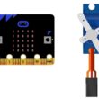
1. ESP8266 NodeMCU (Microcontroller Unit)
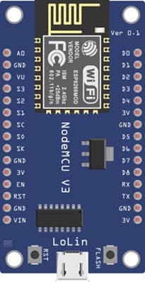
Function: Acts as the central controller of the system. It receives IR signals from the KY-032 sensor, processes them, and sends commands to the servo motor and LCD display accordingly.
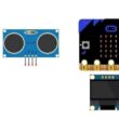
2. KY-032 IR Sensor (IR Receiver Module)
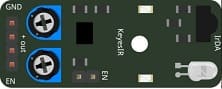
Function: Receives infrared signals from a remote control. When a specific button is pressed, the sensor detects the signal and sends a digital output (HIGH or LOW) to the ESP8266.
In this project, it functions as the IR receiver to detect commands from the remote control. Although KY-032 is mainly for obstacle detection, its IR receiver portion can be used for simple binary (on/off) IR control.
3. IR Remote Control

Function: Sends infrared light pulses to communicate commands to the receiver (KY-032 sensor). Each button corresponds to a unique encoded signal.
It allows the user to remotely trigger door actions (open or close) without touching the system.
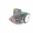
4. Servo Motor (SG90 or MG90S recommended)
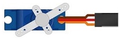
Function: Mechanically moves the door lock or handle by rotating a set number of degrees (e.g., 0° to 90° or 180°) based on the command received.
It is perfect for small door automation projects—provides precise angle control to simulate locking/unlocking or pushing/pulling mechanisms.
5. I2C LCD Display (16x2 or 20x4)

Function: Displays real-time status messages such as “Door Opened,” “Door Closed,” or “Waiting for command.”
Provides user-friendly visual feedback on the state of the door and system operations.
6. Breadboard

Function: Mounts and connect components safely
7. Jumper wires

Function: Establish connections between components and the NodeMCU
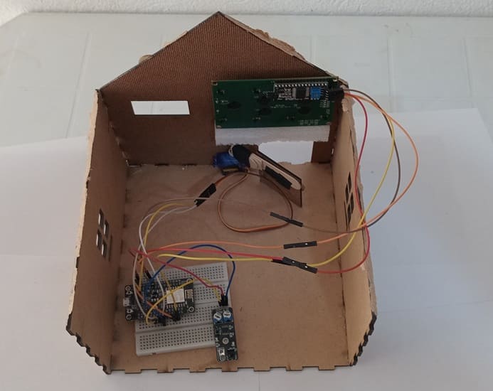
8. Wooden house prototype
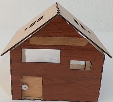
A miniature wooden house represents a real-world structure.
The door mechanism is attached to a servo motor, which rotates to open or close it.
The wooden prototype provides a stable frame for installing components like the IR sensor and LCD screen.
Circuit Connections of system
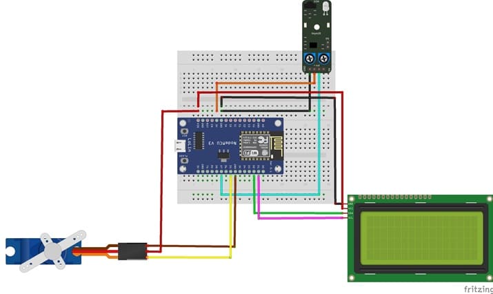
I2C LCD to ESP8266 NodeMCU connections
LCD I2C Screen Pin | ESP8266 NodeMCU Pin |
VCC | VIN |
GND | GND |
SDA | GPIO 4 (D2) |
SCL | GPIO 5 (D1) |
Servo motor to ESP8266 NodeMCU connections
Servo motor | ESP8266 NodeMCU Pin |
Red wire (+) | VIN |
Brown wire (-) | GND |
Yellow wire (Signal) | D5 (GPIO14) |
KY-032 sensor to ESP8266 NodeMCU connections
ESP8266 | ESP8266 NodeMCU |
GND | Pin G |
(+) | 3V pin |
OUT | D7 (GPIO 13) |
Micropython program to control the system
Before running the code, install the necessary libraries:
- Servo (for servo motor)
- i2c_lcd and lcd_api for I2C LCD screen
- ir_rx → for KY-032 sensor
|
1 2 3 4 5 6 7 8 9 10 11 12 13 14 15 16 17 18 19 20 21 22 23 24 25 26 27 28 29 30 31 32 33 34 35 36 37 38 39 40 41 42 43 44 45 46 47 48 49 50 51 52 53 54 55 56 57 58 59 60 61 62 63 64 65 66 67 68 69 70 |
import machine from machine import Pin, SoftI2C from time import sleep from servo import Servo from lcd_api import LcdApi from i2c_lcd import I2cLcd from ir_rx import NEC_16 I2C_ADDR = 0x27 totalRows = 4 totalColumns = 20 # ==== LCD Setup ==== i2c = SoftI2C(scl=Pin(5), sda=Pin(4), freq=10000) #initializing the I2C method for ESP8266 lcd = I2cLcd(i2c, I2C_ADDR, totalRows, totalColumns) def ir_callback(data, addr, ctrl): global ir_data global ir_addr if data > 0: ir_data = data ir_addr = addr print('Data {:02x} Addr {:04x}'.format(data, addr)) # ==== KY-032 IR Sensor Setup ==== ir_gpio=Pin(13, Pin.IN) ir = NEC_16(ir_gpio, ir_callback) ir_data = 0 ir_addr = 0 # ==== Servo Setup ==== motor=Servo(pin=14) motor.move(90) # rotate servo to 90° in order to close door position_door=90 lcd.clear() lcd.move_to(1,1) lcd.putstr("Door closed") # print "Door closed" on LCD display while True: if ir_data > 0: #IR Signal Detection if ir_data==0x0C: # we press the button 1 if position_door==90: lcd.clear() lcd.move_to(1,1) lcd.putstr("The door opens") for i in range(91,19,-1): motor.move(i) # rotate servo to 20° in order to open door sleep(0.1) position_door=20 lcd.clear() lcd.move_to(1,1) lcd.putstr("Door open") if ir_data==0x18: # we press the button 2 if position_door==20: lcd.clear() lcd.move_to(1,1) lcd.putstr("The door closes") for i in range(20,91): motor.move(i) # rotate servo to 90° in order to close door sleep(0.1) position_door=90 lcd.clear() lcd.move_to(1,1) lcd.putstr("Door closed") |
0 comment
Leave a comment
Passion for robotics

Recent tutorials


Robotics workshop

Polpular tutorials


Making robots

Most commented tutorials


Robotic arm

Categories
Smart Home