Reading RFID Badge Data with Arduino and RFID-RC522
Tutorial plan
1- Purpose of the tutorial
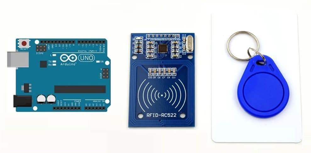
2- RFID-RC522 module and RFID badge
3- Connecting Arduino UNO with RFID-RC522 module
4- Arduino program
Purpose of the tutorial
The purpose of the tutorial on Reading RFID Badge Data Using Arduino and RFID-RC522 is to teach users how to interface an RFID-RC522 module with an Arduino to read RFID badge (tag) data. The tutorial typically covers:
1. Understanding RFID Technology – Explanation of how RFID works and the role of RFID tags and readers.
2. Hardware Setup – Connecting the RFID-RC522 module to an Arduino (e.g., wiring diagram and pin configuration).
3. Library Installation – Installing and using the MFRC522 library for RFID communication.
4. Reading RFID Data – Writing a Microcontroller program (Arduino sketch) to read and display RFID tag UID (Unique Identifier) on a serial monitor or LCD.
RFID-RC522 module and RFID badge
1) RFID-RC522 module
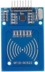
The RFID-RC522 is a popular RFID (Radio Frequency Identification) reader module that operates at 13.56 MHz and is commonly used with microcontrollers like Arduino, ESP32, and Raspberry Pi for reading RFID tags and cards.
Features of the RFID-RC522 Module
Operating Frequency: 13.56 MHz (ISO 14443A standard)
Communication Interface: SPI (also supports I²C and UART with modifications)
Operating Voltage: 3.3V (but can be used with 5V systems like Arduino with logic level conversion)
Reading Range: Up to 5 cm (depending on tag type and antenna quality)
Supported Tags: MIFARE 1K, MIFARE 4K, MIFARE Ultralight, MIFARE DESFire, etc.
How It Works
a) The RFID-RC522 module generates an electromagnetic field at 13.56 MHz.
b) When an RFID tag or card comes near the module, it absorbs energy from the field and sends back its Unique Identifier (UID).
c) The microcontroller (e.g., Arduino) receives this UID and can use it for various applications (e.g., access control, attendance tracking).
Common Applications
Access control systems (e.g., door locks)
Attendance systems (schools, offices)
Inventory tracking
Payment systems (e.g., contactless cards)
Smart parking solutions
2) RFID badge
![]()
An RFID badge is a type of RFID tag that is commonly used for identification, security, and access control. It contains an embedded RFID chip and antenna, allowing it to communicate wirelessly with an RFID reader (such as the RFID-RC522 module).
How an RFID Badge Works ?
a) The RFID reader (e.g., RFID-RC522 module) emits an electromagnetic field.
b) When an RFID badge enters this field, it absorbs energy and activates the embedded chip.
c) The badge then transmits its unique identifier (UID) back to the reader.
d) The microcontroller (e.g., Arduino, ESP32) processes the UID and performs an action (e.g., unlocking a door).
Common Uses of RFID Badges
Employee ID cards for building access.
Student ID badges for attendance tracking.
Library cards for book check-out systems.
Public transportation cards (e.g., NFC-based metro cards).
Event passes for ticket verification.
Would you like a guide on how to read an RFID badge's UID using an Arduino and RFID-RC522?
Connecting Arduino UNO with RFID-RC522 module
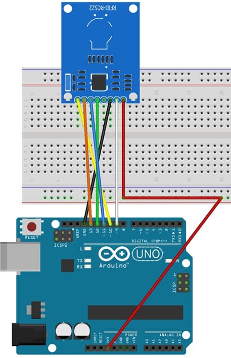
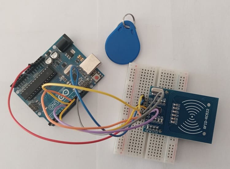
The RFID-RC522 module has 8 pins, but we mainly use 7 pins to connect it with the Arduino UNO.
RFID-RC522 | Arduino UNO | Description |
VCC | 3.3V | Power supply |
GND | GND | Ground |
SDA (SS) | Pin 10 | Slave Select (SS) |
SCK | Pin 13 | SPI Clock (SCK) |
MOSI | Pin 11 | Master Out Slave In (MOSI) |
MISO | Pin 12 | Master In Slave Out (MISO) |
RST | Pin 9 | Reset |
Arduino program
To read RFID tags, we need to install the MFRC522 library in the Arduino IDE.
1- Open Arduino IDE.
2- Go to Sketch → Include Library → Manage Libraries.
3- Search for MFRC522 and install it.
|
1 2 3 4 5 6 7 8 9 10 11 12 13 14 15 16 17 18 19 20 21 22 23 24 25 26 27 28 29 30 31 32 33 34 35 |
#include <SPI.h> #include <MFRC522.h> #define SS_PIN 10 // Slave Select (SDA) connected to pin 10 #define RST_PIN 9 // Reset pin connected to pin 9 MFRC522 rfid(SS_PIN, RST_PIN); // Create an instance of the MFRC522 class void setup() { Serial.begin(9600); // Initialize Serial Monitor SPI.begin(); // Initialize SPI bus rfid.PCD_Init(); // Initialize the RFID module Serial.println("Scan your RFID tag..."); } void loop() { // Check if an RFID card is present if (!rfid.PICC_IsNewCardPresent()) { return; } // Read the RFID card if (!rfid.PICC_ReadCardSerial()) { return; } Serial.print("RFID Tag UID: "); for (byte i = 0; i < rfid.uid.size; i++) { Serial.print(rfid.uid.uidByte[i], HEX); // Print UID in hexadecimal Serial.print(" "); } Serial.println(); rfid.PICC_HaltA(); // Halt the card } |
How It Works ?
1- The RFID-RC522 module waits for an RFID tag to be scanned.
2- When a tag is detected, the UID (Unique Identifier) is read.
3- The UID is displayed in the Serial Monitor in hexadecimal format.
4- The card is then halted to allow a new scan.
How to Test ?
1- Upload the code to your Arduino UNO.
2- Open the Serial Monitor (9600 baud rate).
3- Bring an RFID badge/card close to the RFID-RC522 module.
4- The UID of the tag will appear in the Serial Monitor.
0 comment
Leave a comment
Passion for robotics

Recent tutorials


Robotics workshop

Polpular tutorials


Making robots

Most commented tutorials
Robotic arm

Categories
Smart Home