Read RFID card Data using ESP8266 NodeMCU and RFID-RC522
Tutorial plan
1- Purpose of the tutorial
2- RFID-RC522 module and RFID card
3- Connecting ESP8266 NodeMCU with RFID-RC522 module and LCD I2C Screen
4- Micropython code to Read RFID Card and Display on LCD
Purpose of the tutorial
The purpose of this tutorial is to guide users step by step on how to interface an ESP8266 NodeMCU with an RFID-RC522 module and an LCD I2C display to read and display RFID card data.
1. Understanding RFID Technology
Learn how RFID-RC522 works and how it communicates with ESP8266 via SPI protocol.
Understand how RFID cards store unique identification numbers (UIDs).
2. Interfacing Components with ESP8266 NodeMCU
Learn how to connect the RFID-RC522 module with ESP8266.
Interface an LCD I2C display to show scanned card data.
Use I2C communication to reduce wiring complexity.
3. Writing and Uploading Code
Learn how to use the MFRC522 library to read RFID cards.
Implement Micropython code to read and display card data.
Understand how to process, display, and use RFID data.
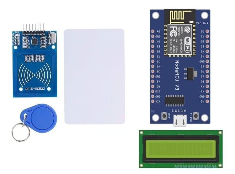
RFID-RC522 module and RFID card
1) RFID-RC522 module
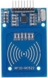
The RFID-RC522 is a low-cost RFID (Radio-Frequency Identification) module that operates at 13.56 MHz and is commonly used for reading and writing RFID tags and cards. It communicates with microcontrollers like ESP8266 NodeMCU, Arduino, and ESP8266 NodeMCU using the SPI, I2C, or UART communication protocols.
How It Works ?
1. The ESP8266 NodeMCU sends a signal to the RFID-RC522 module to check for a nearby RFID card.
2. When a card is detected, its Unique Identifier (UID) is read.
3. The ESP8266 NodeMCU processes the UID and can display it on an LCD I2C display, print it to the serial monitor, or trigger an event.
2- RFID badge :
![]()
An RFID badge is a contactless smart card that contains an embedded RFID chip and an antenna. It is commonly used for identification, access control, attendance tracking, and payment systems. When placed near an RFID reader (like the RC522 module), the badge transmits its Unique Identifier (UID) wirelessly using radio-frequency communication.
How an RFID Badge Works with the RC522 Module
1. The RFID badge contains a chip with a UID (Unique Identifier).
2. When placed near the RFID-RC522 module, the module energizes the badge using electromagnetic waves.
3. The badge transmits its UID back to the reader via radio signals.
4. The ESP8266 NodeMCU receives and processes the UID, displaying it on an LCD I2C display or sending it to another system.
3- RFID white card

An RFID white card is a blank, contactless RFID card that contains an embedded RFID chip and antenna. It is often used for identification, security access, attendance tracking, and cashless payments. These cards are called "white cards" because they are plain and can be customized with printing, logos, or encoded data.
How an RFID White Card Works with the RC522 Module ?
1. The RC522 reader sends an electromagnetic signal to the RFID white card.
2. The card receives power from the signal and transmits its UID (Unique Identifier).
3. The ESP8266 NodeMCU reads and processes the UID.
4. The UID can be displayed on an LCD I2C display, used for authentication, or stored for further use.
Connecting ESP8266 NodeMCU with RFID-RC522 module and LCD I2C Screen
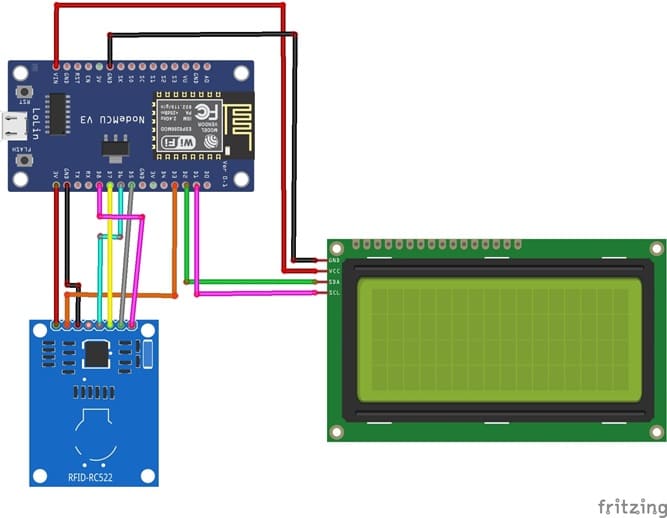
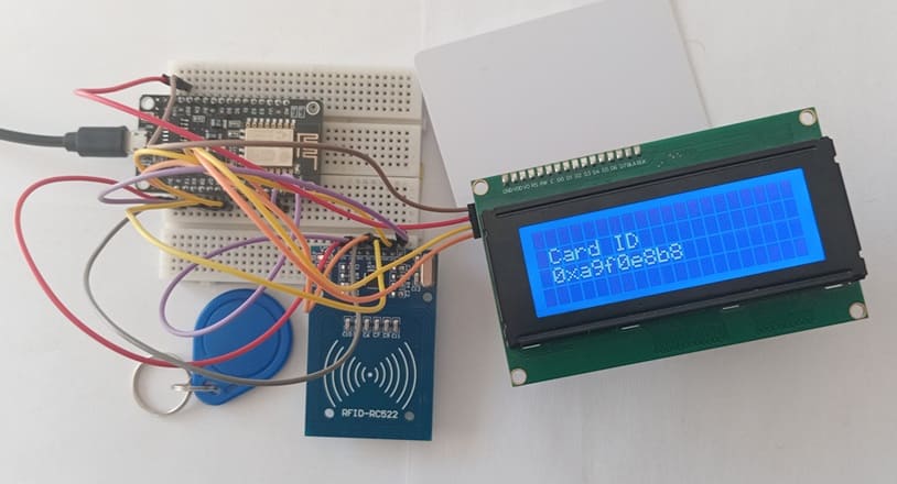
RFID-RC522 to ESP8266 NodeMCU connections
RFID-RC522 Pin | ESP8266 NodeMCU Pin |
SDA | GPIO 15 (D8) |
SCK | GPIO 14 (D5) |
MOSI | GPIO 13 (D7) |
MISO | GPIO 12 (D6) |
GND | GND |
RST | GPIO 0 (D3) |
3V3 | 3V3 |
I2C LCD to ESP8266 NodeMCU connections
LCD I2C Screen Pin | ESP8266 NodeMCU Pin |
VCC | VIN |
GND | GND |
SDA | GPIO 4 (D2) |
SCL | GPIO 5 (D1) |
Micropython code to Read RFID Card and Display on LCD
Before running the code, install the necessary libraries:
- MFRC522 (for RFID module)
- i2c_lcd and lcd_api for I2C LCD screen
|
1 2 3 4 5 6 7 8 9 10 11 12 13 14 15 16 17 18 19 20 21 22 23 24 25 26 27 28 29 30 31 32 33 34 35 36 37 38 39 40 41 42 43 44 45 46 47 48 49 50 51 52 53 54 |
from time import sleep_ms from machine import Pin, SPI, SoftI2C,ADC from mfrc522 import MFRC522 from lcd_api import LcdApi from i2c_lcd import I2cLcd # Define the SPI pins sck = Pin(14, Pin.OUT) mosi = Pin(13, Pin.OUT) miso = Pin(12, Pin.OUT) sda = Pin(15, Pin.OUT) I2C_ADDR = 0x27 totalRows = 4 totalColumns = 20 # Create SPI object and initialize MFRC522 RFID reader spi = SPI(baudrate=100000, polarity=0, phase=0, sck=sck, mosi=mosi, miso=miso) # Initialize I2C LCD (address 0x27, 20x4 LCD) i2c = SoftI2C(sda=Pin(4), scl=Pin(5), freq=400000) #initializing the I2C method for ESP8266 NodeMCU lcd = I2cLcd(i2c, I2C_ADDR, totalRows, totalColumns) def do_read(): while True: rdr = MFRC522(spi, sda) uid = "" <span class="hljs-comment"># Check if an RFID card is present</span> (stat, tag_type) = rdr.request(rdr.REQIDL) if stat == rdr.OK: (stat, raw_uid) = rdr.anticoll() if stat == rdr.OK: # Get the card serial number (UID) uid = ("0x%02x%02x%02x%02x" % (raw_uid[0], raw_uid[1], raw_uid[2], raw_uid[3])) print(uid) lcd.clear() lcd.move_to(1,1) lcd.putstr("Card ID") lcd.move_to(1,2) # Display UID on LCD lcd.putstr(uid) sleep_ms(5000) lcd.clear() lcd.move_to(1,1) lcd.putstr('Scan your card') else: dui="" lcd.clear() lcd.move_to(1,1) lcd.putstr('Scan your card') do_read() |
How the Micropython code works ?
SPI Communication: The ESP8266 NodeMCU uses the SPI protocol to communicate with the RFID-RC522 module. We set up the SPI pins using the Pin class from the machine module.
I2C Communication: The LCD is connected to the ESP8266 NodeMCU using the I2C protocol. The lcd_api library handles I2C communication for displaying text on the LCD.
Reading RFID Card:
- The rfid.request() method checks for the presence of an RFID card.
- The rfid.anticoll() method reads the UID of the card.
- The UID is displayed on both the Serial Monitor and the LCD screen.
Looping for Card Scans:
The program continuously checks for the presence of an RFID card. When a card is detected, it reads the UID and displays it on the LCD. It waits for 5 seconds before checking for another card.
0 comment
Leave a comment
Passion for robotics

Recent tutorials


Robotics workshop

Polpular tutorials


Making robots

Most commented tutorials


Robotic arm

Categories
Smart Home