Obstacle detection system using HC-SR04 sensor and Arduino UNO
Introduction
1- Principle of obstacle detection system using HC-SR04 and Arduino UNO
2- Necessary system components
3- Obstacle detection system wiring diagram
4- Programming the Arduino UNO board
Introduction
An obstacle detection system is a technology designed to identify and alert users or autonomous systems about obstacles or hazards in their environment. These systems are commonly used in various applications, including robotics, autonomous vehicles, drones, industrial automation, and assistive technologies. The primary goal is to enhance safety and prevent collisions by providing real-time information about the presence of obstacles.
Here are some key components and technologies often employed in obstacle detection systems:
Sensors:
Ultrasonic Sensors: These sensors use ultrasonic waves to measure the distance between the sensor and an object. They are commonly used for short-range obstacle detection.
Infrared Sensors: Infrared sensors can detect obstacles by emitting and receiving infrared radiation. They are suitable for both short and medium-range applications.
Lidar (Light Detection and Ranging): Lidar systems use laser beams to measure distances and create a detailed 3D map of the surroundings. Lidar is often used in autonomous vehicles and robotics for accurate obstacle detection.
Radar (Radio Detection and Ranging): Radar systems use radio waves to detect the presence and location of objects. They are effective for long-range obstacle detection and are commonly used in automotive applications.
Computer Vision:
Cameras: Image sensors and cameras can be used to capture visual information, and computer vision algorithms can analyze the images to identify obstacles. This method is widely used in various applications, including surveillance systems and autonomous vehicles.
Depth Sensors: Depth-sensing cameras or sensors, such as time-of-flight (ToF) cameras, provide information about the distance to objects, aiding in obstacle detection.
Data Processing and Fusion:
The raw data from sensors need to be processed and fused to create a comprehensive understanding of the environment. This involves filtering, combining, and interpreting data to accurately identify obstacles.
Algorithms:
Various algorithms, including machine learning and artificial intelligence techniques, can be employed to improve the accuracy and reliability of obstacle detection. These algorithms can adapt to different environments and learn from experience.
Alert Systems:
Once an obstacle is detected, the system needs to communicate this information to the user or the controlling system. This could be through visual alerts, audible alarms, or other communication methods.
Integration with Control Systems:
In many applications, obstacle detection systems are integrated with control systems to enable automated responses, such as slowing down a vehicle or stopping a robot when an obstacle is detected.
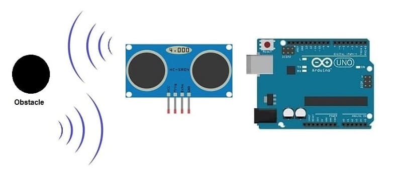
Principle of obstacle detection system using HC-SR04 and Arduino UNO
The obstacle detection system based on HC-SR04, LED, buzzer, and Arduino UNO operates on the principle of using ultrasonic distance measurement to detect obstacles and then providing visual and audible feedback through the LED and buzzer. Here's a step-by-step explanation of the system's principle:
1- Ultrasonic Emission: The HC-SR04 ultrasonic sensor emits a short burst of ultrasonic waves when triggered by the Arduino. This is done by sending a pulse to the trigger (Trig) pin.
2- Wave Reflection: The ultrasonic waves travel through the air until they encounter an obstacle. Upon hitting the obstacle, the waves are reflected back towards the sensor.
3- Echo Reception: The HC-SR04 sensor detects the echoed waves on its echo (Echo) pin.
4- Distance Calculation: The Arduino measures the time interval between sending the trigger signal and receiving the echo. Using the speed of sound in the air (approximately 343 meters per second at 20 degrees Celsius), it calculates the distance to the obstacle.
5- Obstacle Detection: The Arduino then compares the calculated distance with a predefined threshold. If the distance is below a certain threshold, it is determined that an obstacle is present.
6- LED and Buzzer Activation: If an obstacle is detected, the Arduino activates the LED and the buzzer. The LED provides a visual indicator, and the buzzer produces an audible warning.
7- Feedback Control: The system continuously monitors the distance, and if the obstacle moves or is no longer present, the LED and buzzer are deactivated.
Necessary system components
Arduino UNO :
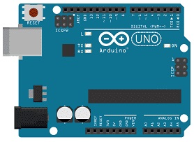
The Arduino Uno is an open-source microcontroller board that is part of the Arduino platform. It is designed for ease of use and is widely used in the maker and hobbyist communities for prototyping and creating various electronic projects.
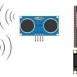
HC-SR04 ultrasonic Sensor
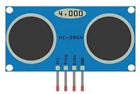
The HC-SR04 is an ultrasonic distance measuring sensor module.
LED
![]()
In an obstacle detection system, an LED (Light Emitting Diode) can be used as a visual indicator to provide feedback about the detection status. The LED can be programmed to turn on or off based on whether an obstacle is detected within a certain range.
Resistance (220 ohm)
![]()
The resistance needed for an LED (Light Emitting Diode) in a circuit is determined by Ohm's Law, which states that the resistance (R) is equal to the voltage (V) divided by the current (I).
Jumper Wires:

For making temporary connections and wiring between components.
Breadboard:

A breadboard is a useful tool for creating temporary electronic circuits. It allows you to connect components without soldering.
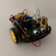
Obstacle detection system wiring diagram
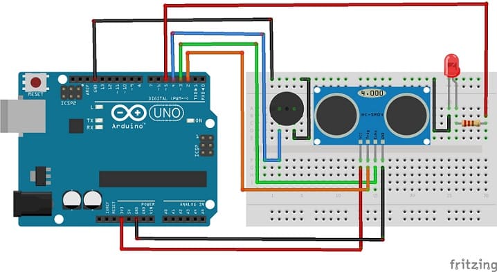
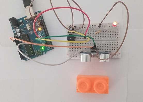
Attaching the HC-SR04 sensor :
- Connect the VCC(+) pin of the HC-SR04 ultrasonic sensor to the 3.3V pin on the Arduino UNO board.
- Connect the Trig pin of the HC-SR04 ultrasonic sensor to pin 4 on the Arduino UNO board.
- Connect the Echo pin of the HC-SR04 ultrasonic sensor to pin 3 on the Arduino UNO board.
- Connect the GND(-) pin of the DHT22 sensor to any ground (GND) pin on the Arduino UNO board.
Attaching the buzzer :
- Connect the (+) terminal of buzzer to pin 4 on the Arduino UNO board.
- Connect the (-) terminal of buzzer to GND pin on the Arduino UNO board.
Attaching the red LED :
- Connect the negative terminal (cathode) of each LED to the ground (GND) of the Arduino UNO board.
- Connect a resistor between the pin 5 and the positive terminal (anode) of the LE
Programming the Arduino UNO board
To program an obstacle detection system using HC-SR04, a buzzer, an LED, and an Arduino UNO, you'll need to follow these steps.
1- import this library :Ultrasonic for HC-SR04 sensor
2- Create a new Arduino script and write the following code :
|
1 2 3 4 5 6 7 8 9 10 11 12 13 14 15 16 17 18 19 20 21 22 23 24 25 26 27 28 29 |
#include "Ultrasonic.h" Ultrasonic ultrasonic(2, 3); // Trig et Echo int buzzer_pin = 4; int redled_pin = 5; void setup() { Serial.begin(9600); pinMode(buzzer_pin, OUTPUT); pinMode(redled_pin, OUTPUT); } void loop () { // Calculate distance int distance = ultrasonic.Ranging(CM); Serial.print("distance= "); Serial.print(distance); Serial.println(" cm"); // Check if obstacle is detected if (distance < 4) { // Activate buzzer and LED digitalWrite(buzzer_pin, HIGH); digitalWrite(redled_pin, HIGH); } else { // Deactivate buzzer and LED digitalWrite(buzzer_pin, LOW); digitalWrite(redled_pin, LOW); } delay(100); } |
0 comment
Leave a comment
Passion for robotics

Recent tutorials


Robotics workshop

Polpular tutorials


Making robots

Most commented tutorials


Robotic arm

Categories
Smart Home