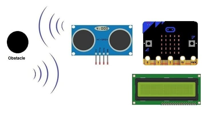
Obstacle detection system using HC-SR04, LCD screen and Micro:bit
1- Principle of obstacle detection system controlled by Micro:bit
2- Necessary system components
3- Obstacle detection system wiring diagram
4- Programming the Micro:bit with Makecode
Principle of obstacle detection system controlled by Micro:bit
An obstacle detection system is a technology designed to identify and alert users or autonomous systems about obstacles or hazards in their environment. These systems are commonly used in various applications, including robotics, autonomous vehicles, drones, industrial automation, and assistive technologies. The primary goal is to enhance safety and prevent collisions by providing real-time information about the presence of obstacles.
The obstacle detection system using HC-SR04, I2C LCD screen, LED, buzzer, and Arduino UNO operates based on the principles of ultrasonic distance measurement and sensor integration. Here's a step-by-step explanation of how the system works:
1- Ultrasonic Distance Measurement (HC-SR04):
The HC-SR04 ultrasonic sensor emits ultrasonic waves using the transducer on the trigger pin.
The waves travel through the air and bounce off any obstacle in their path.
The transducer on the echo pin receives the reflected waves.
2- Calculation of Distance:
The Micro:bit board measures the time it takes for the ultrasonic waves to travel to the obstacle and back.
Using the speed of sound in air (approximately 343 meters per second), the Micro:bit board calculates the distance to the obstacle.
3- Obstacle Detection:
A conditional statement checks if the measured distance is less than a predefined threshold (e.g., 20 cm).
If the distance is less than the threshold, an obstacle is considered detected.
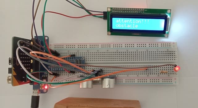
4- Display on I2C LCD Screen:
The I2C LCD screen serves as a user interface by displaying relevant information obstacle detection status.
5- LED Indication:
An LED is used to provide a visual indication of obstacle detection.
The LED is turned on when an obstacle is detected and turned off otherwise.
6- Buzzer Alert:
A buzzer is employed to provide an audible alert when an obstacle is detected.
The buzzer is activated, producing a tone, when the system identifies an obstacle.
Necessary system components
Micro:bit board:

The Micro:bit board is a small, programmable microcontroller board designed for education and beginner-friendly coding projects. It was developed by the BBC, in collaboration with various partners, as a tool to introduce young people to programming and electronics.
The GPIO expansion card for the Micro:bit card

The GPIO expansion board for the Micro:bit board expands the capabilities of the Micro:bit board by adding more input/output (GPIO) pins and additional functionality.
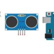
HC-SR04 ultrasonic Sensor
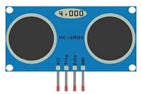
The HC-SR04 is an ultrasonic distance measuring sensor module.
I2C LCD Display (usually 16x2)

This screen is used for displaying a alert message if the HC-SR04 sensor detects an obstacle.
LED
![]()
In an obstacle detection system, an LED (Light Emitting Diode) can be used as a visual indicator to provide feedback about the detection status. The LED can be programmed to turn on or off based on whether an obstacle is detected within a certain range.
Resistance (220 ohm)
![]()
The resistance needed for an LED (Light Emitting Diode) in a circuit is determined by Ohm's Law, which states that the resistance (R) is equal to the voltage (V) divided by the current (I).
Jumper Wires:

For making temporary connections and wiring between components.
Breadboard:

A breadboard is a useful tool for creating temporary electronic circuits. It allows you to connect components without soldering.
Obstacle detection system wiring diagram
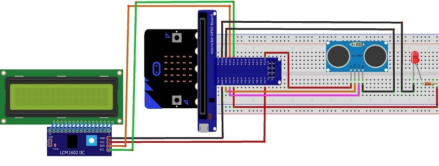
Attaching the I2C LCD Display :
Connect the SDA (data line) of the LCD I2C 1602 display to P20 pin of the Micro:bit board.
Connect the SCL (clock line) of the LCD I2C 1602 display to P19 of the Micro:bit board.
Connect the VCC pin of the LCD I2C 1602 display to the 5V pin of the GPIO board or another energy source .
Connect the GND pin of the LCD I2C 1602 display to GND pin of the Micro:bi board.
Attaching the HC-SR04 sensor :
Connect the VCC(+) pin of the HC-SR04 ultrasonic sensor to the 3.3V pin on the Micro:bit board.
Connect the Trig pin of the HC-SR04 ultrasonic sensor to P0 pin on the Micro:bit board.
Connect the Echo pin of the HC-SR04 ultrasonic sensor to P1 pin on the Micro:bit board.
Connect the GND(-) pin of the HC-SR04 sensor to any ground (GND) pin on the Micro:bit board.
Attaching the red LED :
- Connect the negative terminal (cathode) of each LED to the ground (GND) of the Micro;bit board.
- Connect a resistor between the P2 pin and the positive terminal (anode) of the LED
Programming the Micro:bit with Makecode
To program an obstacle detection system using HC-SR04 sensor, an LED, LCD screen and the Micro:bit , you'll need to follow these steps:
1- Open the MakeCode editor at https://makecode.microbit.org/.
2- Create a new project by clicking on "New Project."
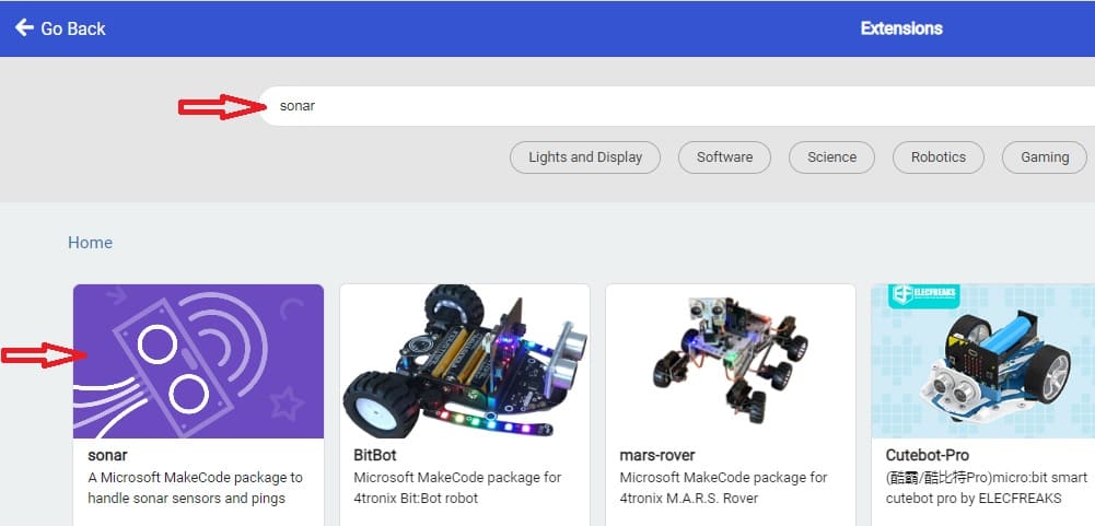
3- Add the HC-SR04 extension:
Look for "Extensions" and click on it.
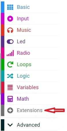
In the search box, type "sonar" to find the bluetooth extension.
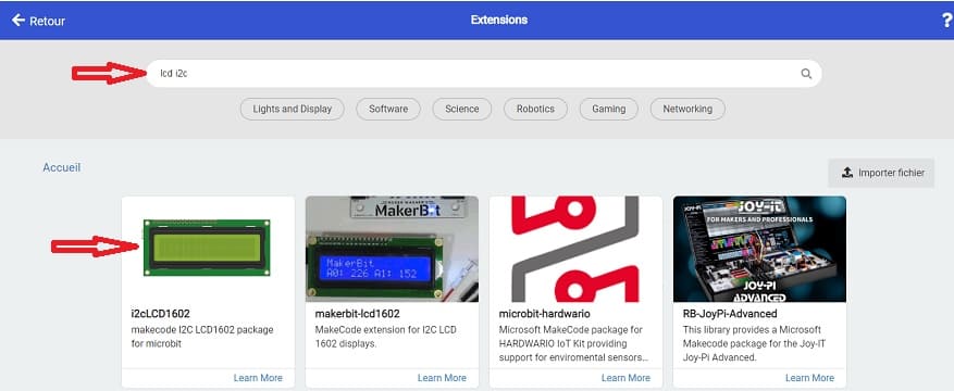
4- In the MakeCode editor, look for the "Extensions" option and click on it.
5- In the search bar, type "I2C LCD," and you should find an extension for the I2C LCD display. Add it to your project.
6- Now, you can start programming the Micro:bit using this Makecode program :
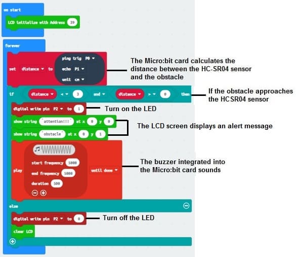
This program continuously monitors the distance using the HC-SR04 sensor, displays the distance on the I2C LCD screen, and triggers the LED and buzzer if an obstacle is detected within a threshold distance (3 cm in this example).
1 comment

ines 11-04-2424
Bonjour Comment avez-vous pu faire fonctionner le HC-SR04 sur une tension de 3,3 volts, s'il vous plaît ? How did you get the HC-SR04 to operate on 3.3 volts, please?
Leave a comment
Passion for robotics

Recent tutorials


Robotics workshop

Polpular tutorials


Making robots

Most commented tutorials


Robotic arm

Categories
Smart Home