Object tracking robot based on Micro:bit board and HC-SR04 sensor
Tutorial plan
1- What is an object tracking robot ?
2- Operation of the Object Tracking Robot controlled by Micro:bit
3- Components of the robot
4- Mounting of the robot
5- Programming the Micro:bit board with Makecode
What is an object tracking robot ?
An object tracking robot is a type of robotic system designed to autonomously detect, follow, and sometimes interact with objects in its environment. These robots typically utilize various sensors, such as cameras, LiDAR (Light Detection and Ranging), ultrasonic sensors, or infrared sensors, to perceive the surroundings and identify target objects.
Once an object is detected, the robot employs algorithms for object tracking to estimate the object's position and trajectory over time. These algorithms can include techniques from computer vision, such as feature detection, motion estimation, and machine learning-based object recognition.
The primary function of an object tracking robot is to autonomously detect, track, and sometimes interact with objects in its environment. Here are some of the key functions and capabilities of an object tracking robot:
1- Object Detection: The robot can identify and locate objects within its field of view using sensors such as cameras, LiDAR, or other proximity sensors.
2- Object Tracking: Once an object is detected, the robot can track its position and movement over time, continuously adjusting its own position and orientation to keep the object within its field of view.
3- Navigation: Object tracking robots often have navigation capabilities, allowing them to move autonomously in the environment while tracking objects. This may involve obstacle avoidance to navigate safely.
4- Interaction: Some object tracking robots are designed to interact with the objects they track. This could involve picking up, manipulating, or otherwise interacting with the object based on programmed instructions or user input.
5- Monitoring and Surveillance: Object tracking robots can be deployed for monitoring and surveillance purposes, automatically tracking and recording the movement of objects or individuals within a specified area.
6- Assistance and Service: In environments such as warehouses, hospitals, or homes, object tracking robots can provide assistance by fetching objects, guiding individuals, or performing other helpful tasks.
7- Security: Object tracking robots can enhance security by monitoring and tracking suspicious or unauthorized objects or individuals in restricted areas.
8- Data Collection and Analysis: By tracking objects and their movements, these robots can collect valuable data for analysis, such as traffic patterns in a retail store or the movement of goods in a warehouse.
Overall, the function of an object tracking robot is to provide autonomous perception and interaction capabilities in various applications, enhancing efficiency, safety, and functionality in diverse environments.
Operation of the Object Tracking Robot controlled by Micro:bit
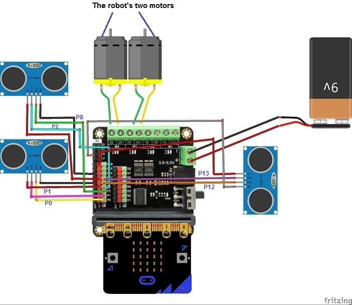
Here's a detailed description of how the object tracking robot based on a Micro:bit board, three HC-SR04 sensors, and a motor driver card operates:
1. Initialization:
Upon powering on, the Micro:bit board initializes and starts running the preloaded code.
The motor driver card is initialized, configuring the GPIO pins connected to the motors to control their direction and speed.
2. Sensor Readings:
The robot continuously reads distance measurements from the three HC-SR04 ultrasonic sensors.
Each sensor emits ultrasonic waves and measures the time it takes for the waves to bounce back, determining the distance to nearby objects.
The Micro:bit board receives these distance readings from the sensors.
3. Object Detection:
Based on the received distance readings, the robot determines the presence and location of nearby objects.
Each sensor provides information about objects within its range, allowing the robot to detect objects from different directions (front, left, and right).
4. Object Tracking Algorithm:
Using the distance readings from the sensors, the robot employs an object tracking algorithm to decide how to move.
The algorithm analyzes which sensor detects the nearest object and determines the appropriate action to track it.
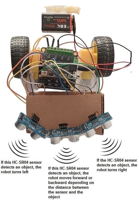
For example:
If an object is detected in front of the robot, it might move forward.
If an object is detected to the left, the robot might turn left to align itself with the object.
If an object approaches the robot, the robot moves backwards
Similarly, if an object is detected to the right, the robot might turn right.
5. Motor Control:
- The Micro:bit board sends control signals to the motor driver card based on the object tracking algorithm's output.
- The motor driver card interprets these signals and adjusts the speed and direction of the motors accordingly.
For example:
- To move forward, the motors spin in the same direction.
- To turn left or right, one motor might stop while the other continues to rotate, causing the robot to turn in the desired direction.
Robot components
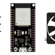
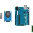
Micro:bit board:

The Micro:bit board is a small, programmable microcontroller board designed for education and beginner-friendly coding projects. It was developed by the BBC, in collaboration with various partners, as a tool to introduce young people to programming and electronics.
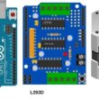
DRIVER EXPANSION for Micro:bit
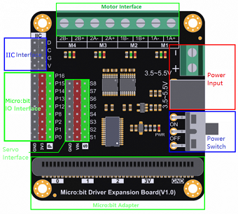
A driver expansion board, such as the L298N motor driver module, acts as an interface between the Micro:bit board and external devices, providing the necessary circuitry to control motors.
4- Wheels and Chassis:
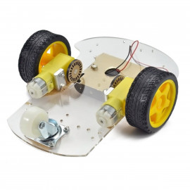
Choose wheels and a chassis suitable for your robot's size and weight requirements. The wheels will be attached to the DC motors to allow the robot to move.
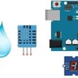
HC-SR04 Ultrasonic Sensors:
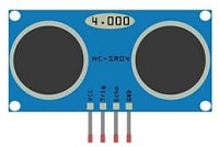
HC-SR04 sensors are commonly used for distance measurement. You'll need at least two of these sensors to detect objects in front of the robot and determine their distance.
Power Supply:
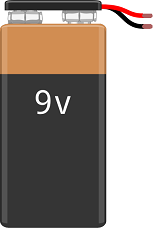
Provide a suitable power supply for the robot. Depending on the power requirements of your components, you may need a battery pack or an external power adapter.
Jumper Wires

Jumper wires will be used to make connections between the components.
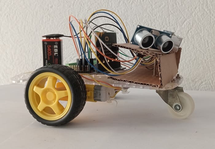
Mounting of the robot
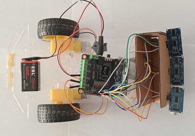
Here's a step-by-step guide to assemble an object tracking robot using Micro:bit, an L298N motor driver module, and HC-SR04 ultrasonic sensors:
1- Gather Components:
Collect all the necessary components mentioned earlier: Micro:bit, L298N motor driver module, DC motors, wheels, HC-SR04 ultrasonic sensors, power supply, jumper wires, breadboard (optional), mounting hardware, and any miscellaneous components.
2- Prepare the Chassis:
Assemble the chassis according to your design. Attach the motors to the chassis using mounting brackets and screws. Mount the wheels securely onto the motor shafts.
3- Connect Motors to Driver card:
Wire the DC motors to the driver module. Connect the two terminals of each motor to the M3 and M4 terminals of Driver module. Ensure that the polarity is correct to control the motor's direction.
4- Wire HC-SR04 Sensors to Micro:bit:
Connect the VCC and GND pins of each HC-SR04 sensor to the appropriate power and ground pins on the Micro:bit. Connect the Trig (trigger) and Echo pins of each sensor to GPIO pins on the Micro:bit.
For the first HC-SR04 sensor
- Connect the VCC(+) pin of the HC-SR04 ultrasonic sensor to the 3.3V pin on the Micro:bit board.
- Connect the Trig pin of the HC-SR04 ultrasonic sensor to P1 pin on the Micro:bit board.
- Connect the Echo pin of the HC-SR04 ultrasonic sensor to P0 pin on the Micro:bit board.
- Connect the GND(-) pin of the DHT22 sensor to any ground (GND) pin on the Micro:bit board.
For the second HC-SR04 sensor
- Connect the VCC(+) pin of the HC-SR04 ultrasonic sensor to the 3.3V pin on the Micro:bit2 board.
- Connect the Trig pin of the HC-SR04 ultrasonic sensor to P8 pin on the Micro:bit board.
- Connect the Echo pin of the HC-SR04 ultrasonic sensor to P2 pin on the Micro:bit board.
- Connect the GND(-) pin of the DHT22 sensor to any ground (GND) pin on the Micro:bit board.
For the third HC-SR04 sensor
- Connect the VCC(+) pin of the HC-SR04 ultrasonic sensor to the 3.3V pin on the Micro:bit board.
- Connect the Trig pin of the HC-SR04 ultrasonic sensor to P13 pin on the Micro:bit board.
- Connect the Echo pin of the HC-SR04 ultrasonic sensor to P12 pin on the Micro:bit board.
- Connect the GND(-) pin of the DHT22 sensor to any ground (GND) pin on the Micro:bit board.
5- Power Supply:
Connect the power supply to the Driver module. Ensure that the voltage levels are compatible with the requirements of all components.
Programming the Micro:bit board with Makecode
1- Open the MakeCode editor at https://makecode.microbit.org/.
2- Create a new project by clicking on "New Project."
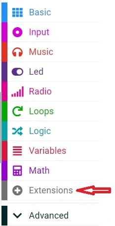
3- Add the HC-SR04 extension:
Look for "Extensions" and click on it.
In the search box, type "sonar" to find the HC-SR04 extension.
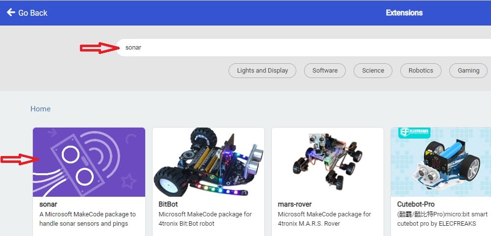
Now, you can start programming the Micro:bit to use the HC-SR04 sensor.
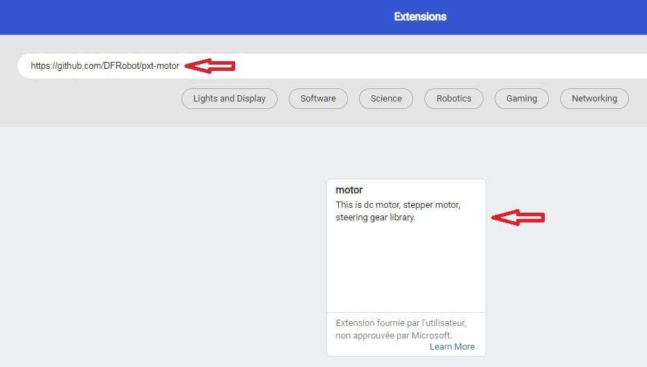
4- Add the Motor extension:
Look for "Extensions" and click on it.
5-Add this link "https://github.com/DFRobot/pxt-motor" in the search for extensions to control the two motors by the Driver card.
Here's a sample MakeCode program to control the robot by Micro:bit board:
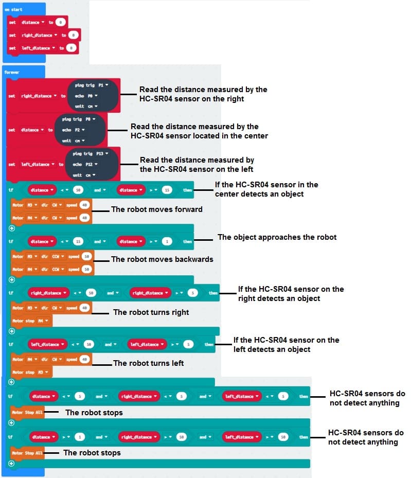
The code should read distance measurements from the ultrasonic sensors and control the motors accordingly.
On Start: Initialize any variables or settings.
Forever Loop:
Continuously perform the following actions:
1- Measure the distance using the HC-SR04 sensor in front of the robot.
2- If an object is detected within a certain distance threshold, adjust the robot's movement to track the object.
Object Tracking Logic:
Use conditional statements to determine the robot's movement based on the distance reading from the sensor.
For example:
1- If the distance is less than a certain value, turn left or right to avoid the obstacle.
2- If the distance is greater, move forward.
3- If an object approaches the robot, the robot moves backwards
Motor Control:
Use motor control blocks to set the speed and direction of the robot's movement.
Activate appropriate motors based on the object tracking logic.
0 comment
Leave a comment
Passion for robotics

Recent tutorials


Robotics workshop

Polpular tutorials


Making robots

Most commented tutorials


Robotic arm

Categories
Smart Home