Object tracking robot based on ESP32 board and HC-SR04 sensor
Tutorial plan
1- What is an object tracking robot ?
2- Operation of the Object Tracking Robot controlled by the ESP32 card
3- Robot components
4- Mounting of robot
5- Programming the ESP32 board with Micropython
What is an object tracking robot ?
An object tracking robot is a type of robotic system designed to autonomously detect, follow, and sometimes interact with objects in its environment. These robots typically utilize various sensors, such as cameras, LiDAR (Light Detection and Ranging), ultrasonic sensors, or infrared sensors, to perceive the surroundings and identify target objects.
Once an object is detected, the robot employs algorithms for object tracking to estimate the object's position and trajectory over time. These algorithms can include techniques from computer vision, such as feature detection, motion estimation, and machine learning-based object recognition.
The primary function of an object tracking robot is to autonomously detect, track, and sometimes interact with objects in its environment. Here are some of the key functions and capabilities of an object tracking robot:
1- Object Detection: The robot can identify and locate objects within its field of view using sensors such as cameras, LiDAR, or other proximity sensors.
2- Object Tracking: Once an object is detected, the robot can track its position and movement over time, continuously adjusting its own position and orientation to keep the object within its field of view.
3- Navigation: Object tracking robots often have navigation capabilities, allowing them to move autonomously in the environment while tracking objects. This may involve obstacle avoidance to navigate safely.
4- Interaction: Some object tracking robots are designed to interact with the objects they track. This could involve picking up, manipulating, or otherwise interacting with the object based on programmed instructions or user input.
5- Monitoring and Surveillance: Object tracking robots can be deployed for monitoring and surveillance purposes, automatically tracking and recording the movement of objects or individuals within a specified area.
6- Assistance and Service: In environments such as warehouses, hospitals, or homes, object tracking robots can provide assistance by fetching objects, guiding individuals, or performing other helpful tasks.
7- Security: Object tracking robots can enhance security by monitoring and tracking suspicious or unauthorized objects or individuals in restricted areas.
8- Data Collection and Analysis: By tracking objects and their movements, these robots can collect valuable data for analysis, such as traffic patterns in a retail store or the movement of goods in a warehouse.
Overall, the function of an object tracking robot is to provide autonomous perception and interaction capabilities in various applications, enhancing efficiency, safety, and functionality in diverse environments.
Operation of the Object Tracking Robot controlled by the ESP32 card
Building an object tracking robot using an ESP32 microcontroller, an L298N motor driver module, and HC-SR04 ultrasonic sensors involves several steps. Here's a general overview of how you can set it up and operate it:
1- Hardware Setup:
Connect the motors to the L298N motor driver module. The L298N module controls the speed and direction of the motors.
Connect the HC-SR04 ultrasonic sensors to the ESP32. You typically need four connections for each sensor: VCC, GND, Trig (trigger), and Echo.
2-Programming:
Write the firmware for the ESP32 microcontroller. You can use Arduino IDE or any other compatible development environment for programming the ESP32.
Use the ESP32's GPIO pins to interface with the L298N module and control the motor movements.
Write code to read data from the HC-SR04 sensors and calculate the distance to objects in front of the robot.
Implement logic for object tracking, such as turning the robot to face the detected object or following it as it moves within the sensor range.
You may also need to implement collision avoidance logic to prevent the robot from running into obstacles.
3- Operation:
Power on the robot and ensure that all connections are secure.
The robot will start scanning its surroundings using the HC-SR04 sensors.
When an object is detected within the specified range, the robot will adjust its movement to track the object.
Depending on your implementation, the robot may follow the object, maintain a constant distance from it, or perform other tracking behaviors.
Monitor the robot's behavior and make adjustments to the code as needed to improve its tracking performance.
You can control the robot's behavior by adjusting parameters in the code, such as the detection range, tracking algorithm, and motor control logic.
4- Testing and Iteration:
Test the robot in different environments and scenarios to evaluate its performance.
Make adjustments to the code and hardware based on your testing results to optimize the robot's tracking capabilities.
Iterate on the design, adding additional features or improving existing ones to make the robot more versatile and reliable.
By following these steps, you can create an object tracking robot using an ESP32 microcontroller, an L298N motor driver module, and HC-SR04 ultrasonic sensors.
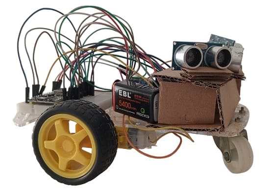
Robot components
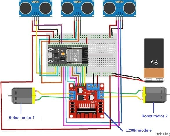
To build an object tracking robot using an ESP32 microcontroller, an L298N motor driver module, and HC-SR04 ultrasonic sensors, you'll need the following components:
1- ESP32 Microcontroller:
The ESP32 is a powerful microcontroller with built-in Wi-Fi and Bluetooth capabilities. It will serve as the brain of the robot, controlling its movements and interacting with sensors.
2- L298N Motor Driver Module:
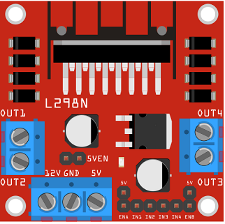
The L298N module is a dual H-bridge motor driver that allows you to control the speed and direction of two DC motors independently. It provides bidirectional control for each motor, making it suitable for driving the wheels of the robot.
3- DC Motors:
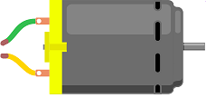
You'll need two DC motors to drive the wheels of the robot. The L298N module will control the speed and direction of these motors based on the commands received from the ESP32.
4- Wheels and Chassis:
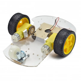
Choose wheels and a chassis suitable for your robot's size and weight requirements. The wheels will be attached to the DC motors to allow the robot to move.
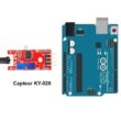
5- HC-SR04 Ultrasonic Sensors:
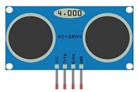
HC-SR04 sensors are commonly used for distance measurement. You'll need at least two of these sensors to detect objects in front of the robot and determine their distance.
6- Power Supply:
Provide a suitable power supply for the ESP32, L298N module, DC motors, and sensors. Depending on the power requirements of your components, you may need a battery pack or an external power adapter.
7- Jumper Wires

Jumper wires will be used to make connections between the components.
8- Breadboard:
A breadboard can be used to create a temporary circuit for testing and prototyping.
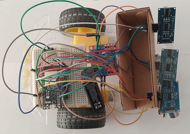
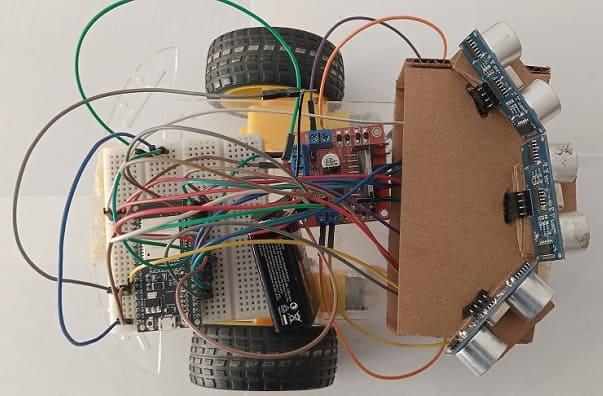
Assembly of the robot
Here's a step-by-step guide to assemble an object tracking robot using an ESP32 microcontroller, an L298N motor driver module, and HC-SR04 ultrasonic sensors:
1- Gather Components:
Collect all the necessary components mentioned earlier: ESP32 microcontroller, L298N motor driver module, DC motors, wheels, HC-SR04 ultrasonic sensors, power supply, jumper wires, breadboard (optional), mounting hardware, and any miscellaneous components.
2- Prepare the Chassis:
Assemble the chassis according to your design. Attach the motors to the chassis using mounting brackets and screws. Mount the wheels securely onto the motor shafts.
3- Connect Motors to L298N Module:
Wire the DC motors to the L298N motor driver module. Connect the two terminals of each motor to the OUT1/OUT2 and OUT3/OUT4 terminals of the L298N module. Ensure that the polarity is correct to control the motor's direction.
4- Connect L298N Module to ESP32:
Connect the control pins of the L298N module to the GPIO pins of the ESP32 microcontroller. You'll typically need connections for controlling the motor direction (e.g., IN1, IN2, IN3, IN4) and PWM pins for speed control (e.g., ENA, ENB).
- Connect pin N°23 of the ESP32 board to the ENA pin of the L298N module.
- Connect pin N°22 of the ESP32 board to pin IN1 of the L298N module.
- Connect pin N°21 of the ESP32 board to pin IN2 of the L298N module.
- Connect pin N°19 of the ESP32 board to pin IN3 of the L298N module.
- Connect pin N°18 of the ESP32 board to pin IN4 of the L298N module.
- Connect pin N°5 of the ESP32 board to the ENB pin of the L298N module.
- Connect the GND pin of the ESP32 board to the GND pin of the L298N module.
5- Wire HC-SR04 Sensors to ESP32:
Connect the VCC and GND pins of each HC-SR04 sensor to the appropriate power and ground pins on the ESP32. Connect the Trig (trigger) and Echo pins of each sensor to GPIO pins on the ESP32.
For the first HC-SR04 sensor
- Connect the VCC(+) pin of the HC-SR04 ultrasonic sensor to the 3.3V pin on the ESP32 board.
- Connect the Trig pin of the HC-SR04 ultrasonic sensor to GPIO16 pin on the ESP32 board.
- Connect the Echo pin of the HC-SR04 ultrasonic sensor to GPIO17 pin on the ESP32 board.
- Connect the GND(-) pin of the DHT22 sensor to any ground (GND) pin on the ESP32 board.
For the second HC-SR04 sensor
- Connect the VCC(+) pin of the HC-SR04 ultrasonic sensor to the 3.3V pin on the ESP32 board.
- Connect the Trig pin of the HC-SR04 ultrasonic sensor to GPIO2 pin on the ESP32 board.
- Connect the Echo pin of the HC-SR04 ultrasonic sensor to GPIO4 pin on the ESP32 board.
- Connect the GND(-) pin of the DHT22 sensor to any ground (GND) pin on the ESP32 board.
For the third HC-SR04 sensor
- Connect the VCC(+) pin of the HC-SR04 ultrasonic sensor to the 3.3V pin on the ESP32 board.
- Connect the Trig pin of the HC-SR04 ultrasonic sensor to GPI12 pin on the ESP32 board.
- Connect the Echo pin of the HC-SR04 ultrasonic sensor to GPI15 pin on the ESP32 board.
- Connect the GND(-) pin of the DHT22 sensor to any ground (GND) pin on the ESP32 board.
6- Power Supply:
Connect the power supply to the ESP32, L298N module, and HC-SR04 sensors. Ensure that the voltage levels are compatible with the requirements of all components.
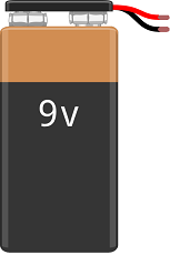
- Connect the 5V pin of the ESP32 board to the (+) pin of the 9V battery
- Connect the GND pin of the ESP32 board to the (-) terminal of the 9V battery
- Connect the 12V pin of the L298N module to the (+) pin of the 9V battery
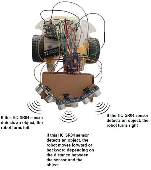
7- Mount Sensors:
Mount the HC-SR04 sensors on the front of the robot chassis facing forward. Ensure that they have a clear line of sight to detect objects in front of the robot.
Programming the ESP32 board with Micropython
Programming an object tracking robot using Micropython on an ESP32 microcontroller, L298N motor driver module, and HC-SR04 ultrasonic sensors involves setting up GPIO pins for motor control and sensor interfacing, implementing object detection and tracking logic, and controlling the motors based on the detected objects.
You need to import DCMotor.py library to control the two motor and hc-sr04.py library to control the HC-SR04 sensors .
Here's a basic example code to get you started:
|
1 2 3 4 5 6 7 8 9 10 11 12 13 14 15 16 17 18 19 20 21 22 23 24 25 26 27 28 29 30 31 32 33 34 35 36 37 38 39 40 41 42 43 |
from DCMotor import DCMotor from machine import Pin, PWM from hcsr04 import HCSR04 import time # Define motor pins frequency = 15000 pin1 = Pin(22, Pin.OUT) pin2 = Pin(21, Pin.OUT) pin3 = Pin(19, Pin.OUT) pin4 = Pin(18, Pin.OUT) enable = PWM(Pin(23), frequency) enable1 = PWM(Pin(5), frequency) dc_motor = DCMotor(pin1, pin2, enable) dc_motor = DCMotor(pin1, pin2, enable, 350, 1023) dc_motor1 = DCMotor(pin3, pin4, enable1) dc_motor1 = DCMotor(pin3, pin4, enable1, 350, 1023) # Define HC-SR04 sensor pins sensor_right = HCSR04(trigger_pin=16,echo_pin=17,echo_timeout_us=1000000) sensor = HCSR04(trigger_pin=2,echo_pin=4,echo_timeout_us=1000000) sensor_left = HCSR04(trigger_pin=12,echo_pin=15,echo_timeout_us=1000000) while True : <span class="hljs-comment"># Get distances from HC-SR04 sensors</span> distance_left = sensor_left.distance_cm() distance = sensor.distance_cm() distance_right = sensor_right.distance_cm() <span class="hljs-comment"># Adjust motor speeds based on distance</span> if ((distance<50) and (distance>10)): # If objects detected by HC-SR04 sensor in the center dc_motor.forward(60) # the robot moves forward dc_motor1.forward(60) if ((distance<10) and (distance_right>10)): # If the object approaches the HC-SR04 sensor dc_motor.backwards(60) # The robot is moving backwards dc_motor1.backwards(60) if ((distance_right<50) and (distance_right>10)): # If the HC-SR04 sensor on the right detects an object dc_motor1.forward(60) # The robot turns right dc_motor.stop() if ((distance_left<50) and (distance_left>10)): # If the HC-SR04 sensor on the left detects an object dc_motor.forward(60) # The robot turns left dc_motor1.stop() if ((distance>50) and(distance_right>50)and(distance_left>50)): # If no objects detected dc_motor.stop() # The robot stops dc_motor1.stop() time.sleep(0.5) |
1 comment

DINKIN 16-01-2525
https://www.robotique.site/wp-content/uploads/2024/02/hc-sr04.py Link broken 404 error
Leave a comment
Passion for robotics

Recent tutorials


Robotics workshop

Polpular tutorials


Making robots

Most commented tutorials


Robotic arm

Categories
Smart Home