Mobile system for tracking a moving object based on Micro:bit and HC-SR04
Introduction
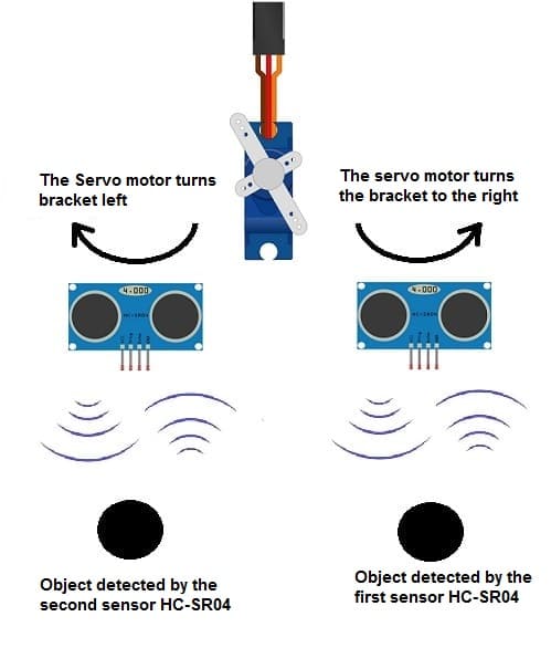
1- How does the mobile system for tracking a moving object work ?
2- Necessary system components
3- System Wiring Diagram
4- Program the Micro:bit board with Makecode to control the system
Introduction
A mobile system for tracking a moving object is a technological solution that utilizes mobile devices such as smartphones or tablets equipped with GPS (Global Positioning System) capabilities to monitor and record the real-time location of an object as it moves. This system typically consists of a mobile application installed on the tracking device, which continuously collects location data through GPS sensors. The collected data is then transmitted to a central server or cloud-based platform for processing, storage, and analysis.
Key components of a mobile tracking system include:
Mobile Application: A software application installed on a mobile device that collects location data using GPS sensors and facilitates communication with the server backend.
GPS Technology: Utilizes GPS technology embedded within the mobile device to determine its precise geographical location.
Server Backend: A centralized server infrastructure responsible for receiving, processing, and storing location data collected from multiple mobile devices. The server backend often includes databases for data storage, APIs for communication with mobile applications, and algorithms for data analysis.
Communication Protocol: Defines the method of communication between the mobile application and the server backend, ensuring secure and efficient data transmission.
Data Storage and Management: Involves the storage and management of location data collected from various mobile devices, typically in a database or cloud-based storage solution.
Visualization and Reporting: Provides tools for visualizing the tracked object's movements on maps, generating reports, and setting up alerts for specific events (e.g., entering or leaving predefined areas).
User Interface: Offers an intuitive interface for users to interact with the tracking system, view real-time and historical location data, and configure tracking settings.
A mobile tracking system can be used for various purposes, including fleet management, asset tracking, personal safety, logistics, and location-based services. It enables businesses and individuals to monitor the whereabouts of valuable assets, vehicles, or people in real-time, leading to improved efficiency, security, and decision-making.
How does the mobile system for tracking a moving object work ?
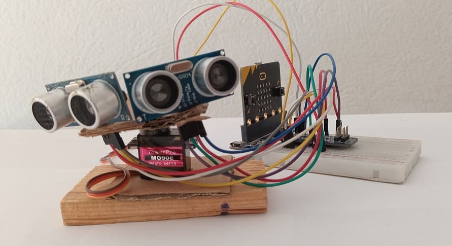
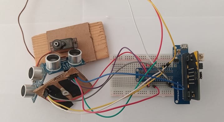
Creating a mobile system to track a moving object using a Micro:bit, two HC-SR04 ultrasonic distance sensors, and a servo motor can be an interesting project. Here's a basic overview of how you can put these components together:
1- Hardware Setup:
Connect two HC-SR04 ultrasonic sensors to the Micro:bit. Each of the two sensors requires four connections: VCC, GND, Trig (trigger), and Echo. Connect VCC and GND to the appropriate pins on the Micro:bit (e.g., 3V and GND pins). Connect the Trig pin of each the two sensors to a digital output pin on the Micro:bit and connect the Echo pin to a digital input pin.
Connect the servo motor to the Micro:bit. Servo motors generally have three wires: power, ground, and control. Connect the power wire (usually red or orange) to 5V pin on the GPIO baord for Micro:bit, the ground wire (usually brown or black) to a GND pin, and the control wire (usually yellow or white) to a PWM-capable pin (e.g., Pin 0).
2- Software Implementation:
Write code for the Micro:bit to control the two HC-SR04 sensors and the servo motor. You'll need to use the Micro:bit's programming environment, which supports languages like Makecode.
The code should read the distance measured by the HC-SR04 sensor using the trigger and echo pins. When the object is detected within a certain range, the Micro:bit should calculate the angle to turn the servo motor.
Use the servo motor to turn in the direction of the detected object. You'll need to adjust the angle of the servo motor based on the position of the detected object.
Algorithm:
Start by triggering the two HC-SR04 sensors to send an ultrasonic pulse.
Measure the time it takes for the pulse to bounce back (i.e., the time taken for the echo pin to go high).
Use this time to calculate the distance to the object.
If the distance is within the desired range, calculate the angle to turn the servo motor based on the position of the object.
Adjust the angle of the servo motor to track the object.
Testing and Refinement:
Test your system to ensure that it accurately tracks moving objects within the desired range.
Adjust parameters such as the distance threshold and servo motor angle to optimize performance.
Debug any issues that arise during testing and refine your code as needed.
By following these steps, you can create a mobile system that tracks moving objects using a Micro:bit board, two HC-SR04 sensor, and servo motor. This project combines hardware interfacing, sensor data processing, and motor control to achieve object tracking functionality.
Necessary system components
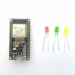
Micro:bit board:

The Micro:bit board is a small, programmable microcontroller board designed for education and beginner-friendly coding projects. It was developed by the BBC, in collaboration with various partners, as a tool to introduce young people to programming and electronics.
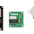
The GPIO expansion card for the Micro:bit card

The GPIO expansion board for the Micro:bit board expands the capabilities of the Micro:bit board by adding more input/output (GPIO) pins and additional functionality.
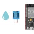
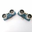
Two HC-SR04 ultrasonic Sensors
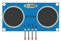
The HC-SR04 ultrasonic sensor is a popular and inexpensive component commonly used in robotics, IoT projects, and various other applications where distance measurement is needed.
Servo motor:
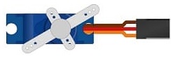
A servo motor is a rotary actuator that allows for precise control of angular position. It consists of a motor, a set of gears, a control circuit, and a feedback system. Servo motors are widely used in various applications such as robotics, RC (remote-controlled) vehicles, industrial automation, and more.
Jumper Wires:

For making temporary connections and wiring between components.
Breadboard:

A breadboard is a useful tool for creating temporary electronic circuits. It allows you to connect components without soldering.
System Wiring Diagram
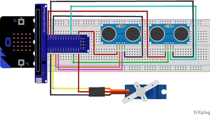
Attaching the first HC-SR04 sensor :
- Connect the VCC(+) pin of the HC-SR04 ultrasonic sensor to the 3.3V pin on the Micro:bit board.
- Connect the Trig pin of the HC-SR04 ultrasonic sensor to P1 pin on the Micro:bit board.
- Connect the Echo pin of the HC-SR04 ultrasonic sensor to P2 pin on the Micro:bit board.
- Connect the GND(-) pin of the DHT22 sensor to any ground (GND) pin on the Micro:bit board.
Attaching the second HC-SR04 sensor :
- Connect the VCC(+) pin of the HC-SR04 ultrasonic sensor to the 3.3V pin on the Micro:bit board.
- Connect the Trig pin of the HC-SR04 ultrasonic sensor to P8 pin on the Micro:bit board.
- Connect the Echo pin of the HC-SR04 ultrasonic sensor to P12 pin on the Micro:bit board.
- Connect the GND(-) pin of the DHT22 sensor to any ground (GND) pin on the Micro:bit board.
Attaching the servo motor :
- Connect the red wire from the servo to the 5V pin of the Micro:bit board.
- Connect the yellow wire from the servo to the P0 pin of the Micro:bit board.
- Connect the brown wire from the servo to the GND pin of the Micro:bit board.
Program the Micro:bit board with Makecode to control the system
To create a program using MakeCode for a mobile system that tracks a moving object using a Micro:bit board, two HC-SR04 sensors, and a servo motor, you can follow these steps:
1- Open the MakeCode editor at https://makecode.microbit.org/.
2- Create a new project by clicking on "New Project."
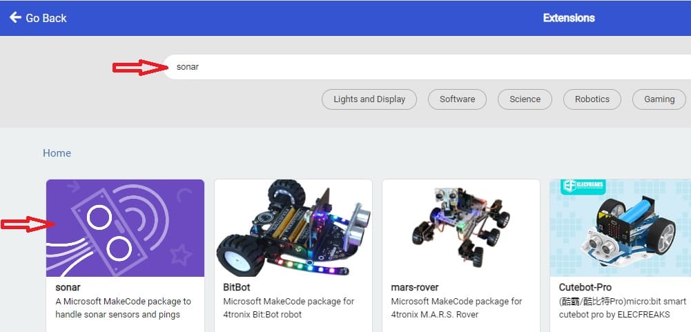
3- Add the HC-SR04 extension:
Look for "Extensions" and click on it.
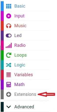
In the search box, type "sonar" to find the HC-SR04 extension.
4- Now, you can start programming the Micro:bit to use the HC-SR04 sensor.
- Initialize Variables: Start by initializing variables to store sensor data and servo motor angles.
- Setup: Configure pins for the HC-SR04 sensors and the servo motor.
- Main Loop:
Read distances from both HC-SR04 sensors.
Determine the angle to turn the servo motor based on the difference between the distances measured by the two sensors.
Adjust the servo motor angle to track the moving object.
Here's a sample MakeCode program to achieve this:
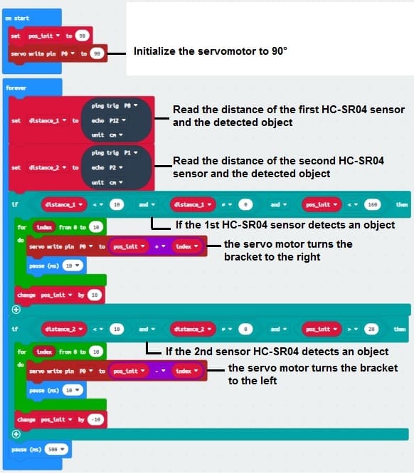
This code sets up two HC-SR04 sensors connected to Pins 8, 12 (first HC-SR04 sensor) and Pins 1, 2 (second HC-SR04 sensor) respectively. It continuously measures distances from both sensors and adjusts the servo motor angle to track a moving object based on the difference in distances. Adjustments are made to the servo motor angle to steer towards the side with more distance detected. Ensure to adjust servo and sensor pins accordingly based on your wiring.
0 comment
Leave a comment
Passion for robotics

Recent tutorials


Robotics workshop

Polpular tutorials


Making robots

Most commented tutorials


Robotic arm

Categories
Smart Home