Micro:bit robot controlled by joystick
Tutorial plan
1- Operation of Micro:bit robot controlled by joystick
2- Components of the robot
3- Mounting of the robot
4- Programming the Micro:bit board with Makecode
Operation of Micro:bit robot controlled by joystick
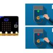
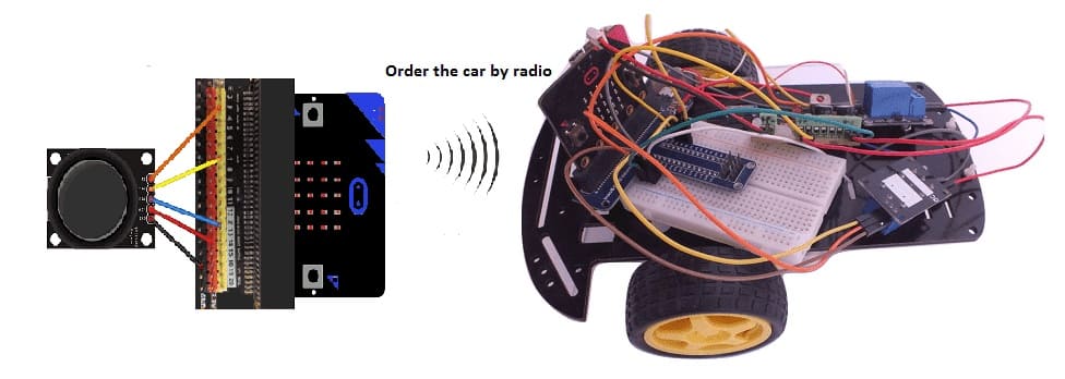
The operation of the Micro:bit robot involves two Micro:bit boards communicating wirelessly to enable joystick-based control of a two-wheeled car kit. Below is a detailed description of the operation:
1- Controller Micro:bit (Transmitter):
A joystick module is connected to the Micro:bit's GPIO pins to capture user input.
The joystick's position (X and Y axes) is read as analog signals, converted into directional commands, and transmitted via the Micro:bit's built-in radio module.
2- Robot Micro:bit (Receiver):
a) Receives the directional commands sent by the transmitter.
b) Controls the two-wheel car kit's motors using relay modules connected to the Micro:bit GPIO pins.
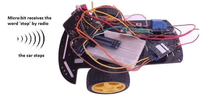
c) Executes forward, left, right, and stop commands based on the received signals.
Components of the robot
1- Joystick (Controller):
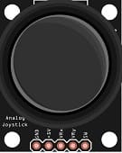
X-axis: Controls left-right movement.
Y-axis: Controls forward-backward movement.
Analog outputs of the joystick are connected to Micro:bit's pins (e.g., P1 for X and P2 for Y).
2- Microbits:
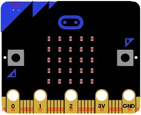
Both Micro:bits use the same radio channel to send and receive commands.
The transmitter sends directional commands ("FORWARD", "BACKWARD", "LEFT", "RIGHT", "STOP").
3- Relay Modules:

Each relay module controls one motor.
The relays switch the motors on/off based on the Micro:bit's digital output pins (e.g., P8 and P12).
Two-Wheel Car Kit:
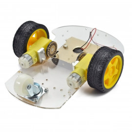
Motors drive the left and right wheels.
Motor speed and direction are indirectly controlled by the relay states.
Power Supply:
Provide a suitable power supply for the robot.
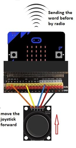
Mounting the joystick with Micro:bit
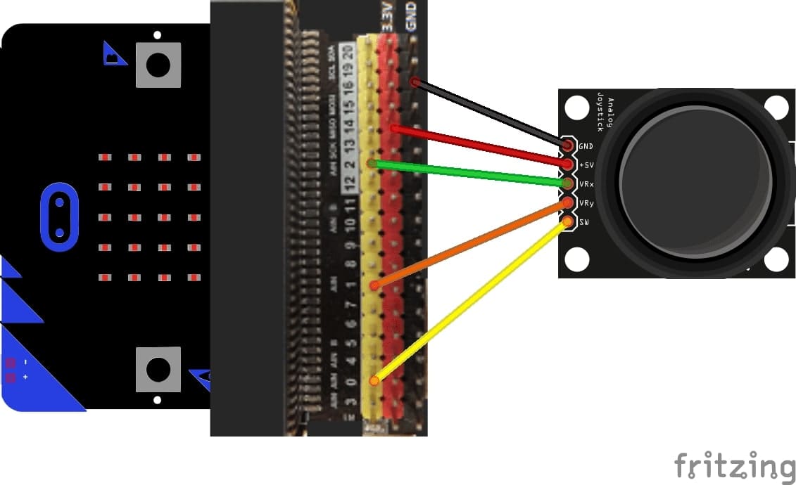
We connect:
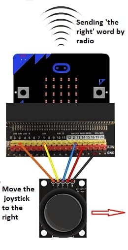
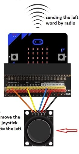
The +5V pin of the 3.3V joystick of the micro:bit
The GND pin of the joystick to the GND of the micro:bit
The VRx pin of the joystick to the pin P2 of the micro:bit
VRy pin from joystick to pin P1 from micro:bit
Pin SW from joystick to pin P0 from micro:bit
Mounting of the robot
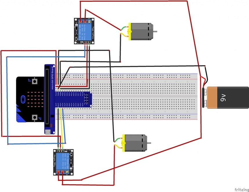
To make the robot assembling, we connect :
1- For the first relay:
pin S to pin P0 of the Micro:bit board
the pin (+) to pin 3.3V of the Micro:bit board
the pin (-) to the GND of the Micro:bit board
the pin ON to an energy of 5V
2- For the second relay:
pin S to pin P1 of the Micro:bit board
pin (+) to pin 3.3V of the Micro:bit board
pin (-) to the GND of the Micro:bit board
pin ON to an energy of 5V
3- For each of the two motors:
the first terminal to the COM pin of the relay
the second terminal to the GND terminal of the Micro:bit board
Programming the Micro:bit board with Makecode
1- Transmitter Code (Controller Micro:bit)
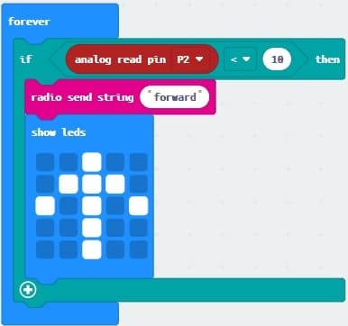
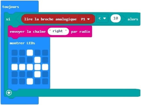
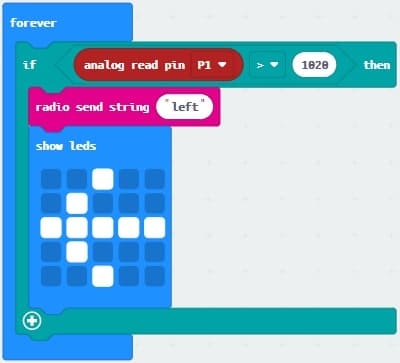
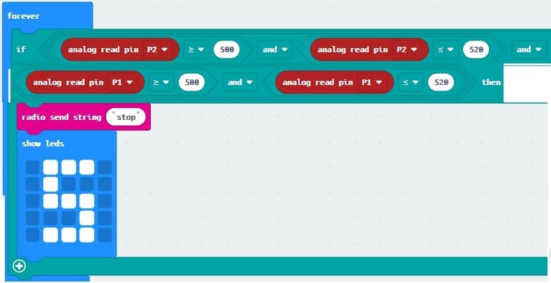
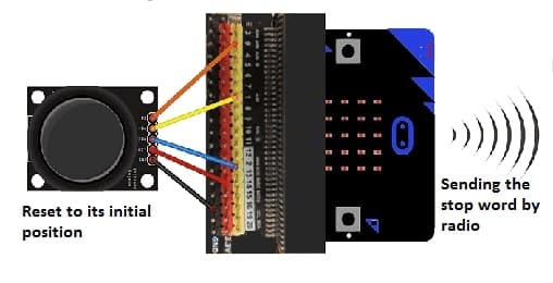
The joystick's position is read as analog values, converted into directional commands, and sent via radio.
a) Based on the joystick's position:
Forward: Joystick pushed up.
Left: Joystick pushed left.
Right: Joystick pushed right.
Stop: Joystick centered.
b) The corresponding direction is sent as a string (e.g., "FORWARD") via radio.
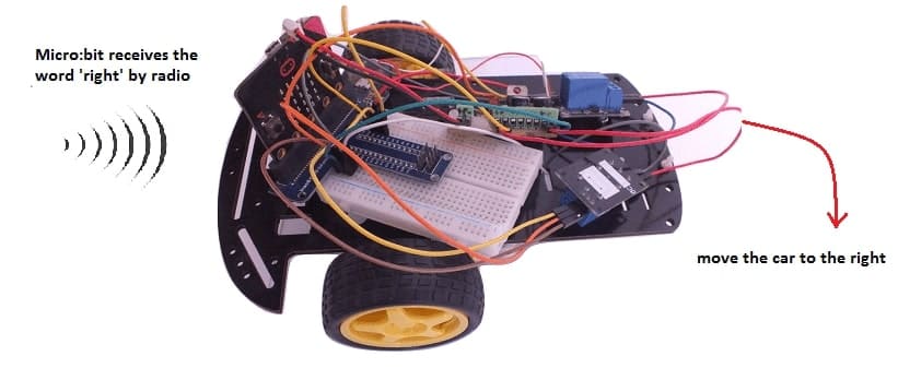
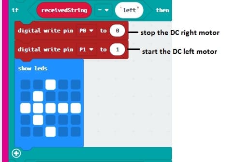
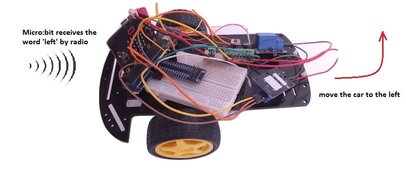
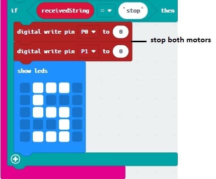
Receiver Code (Robot Micro:bit)
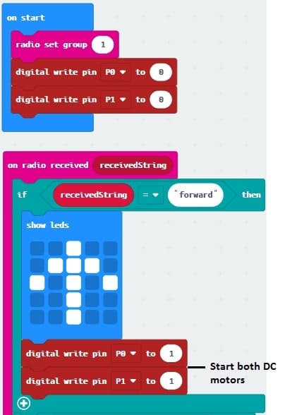
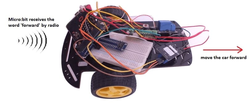
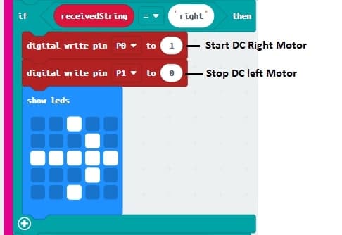
The receiver interprets the direction commands and controls the relay modules accordingly.
3- Steps to Test and Operate
a) Assemble the robot with the motor and relay connections.
b) Ensure the joystick is correctly connected to the controller Micro:bit.
c) Upload the transmitter code to the controller Micro:bit.
d) Upload the receiver code to the robot Micro:bit.
e) Power on both Micro:bits and test the joystick controls.
