Micro:bit fire detection system
Tutorial plan
1- Fire detection system
2- How the Micro:bit fire detection system works ?
3- Micro:bit fire detection system components
4- Mounting Micro:bit with KY-026 sensor, and Buzzer
5- Program Micro:bit with Makecode
Fire detection system
A fire detection system can be implemented using various sensors and technologies, depending on the detection method. Below is an explanation of different approaches to creating a fire detection system, as well as a guide to building one using a microcontroller, sensors, and optional notification mechanisms.
Approaches for Fire Detection
1- Sensor-Based Detection:
Flame Sensors: Detect infrared (IR) radiation emitted by flames.
Temperature Sensors: Detect a rapid rise in temperature.
Smoke Sensors: Detect particles in the air caused by smoke (e.g., MQ-2, MQ-135 sensors).
Gas Sensors: Detect gases like carbon monoxide (CO) or liquefied petroleum gas (LPG) released during combustion.
2- Image-Based Detection:
Use cameras and computer vision algorithms to detect flames, smoke, or heat patterns in the environment.
3- Hybrid Systems:
Combine multiple types of sensors (e.g., flame + smoke + temperature) for robust fire detection.
Applications of Fire Detection System
1- Home Safety: Detect fires in kitchens or living spaces.
2- Industrial Monitoring: Detect fires in factories or warehouses.
3- Smart Cities: Monitor public spaces for fire hazards.
4- Forests: Early detection of wildfires using IoT and image-based detection.
How the Micro:bit fire detection system works ?
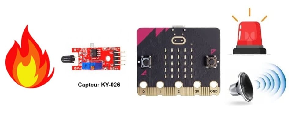
The Micro:bit Fire Detection System using the KY-026 Flame Sensor, a Buzzer, and an LED works by detecting the infrared light emitted by flames.
1- Flame Detection:
The KY-026 flame sensor continuously monitors its surroundings for infrared radiation.
When a flame is detected, the sensor sends a LOW signal (0) to the Micro:bit via its digital output (DO) pin.
2- Processing by Micro:bit:
The Micro:bit reads the sensor's output.
If a flame is detected:
a) The buzzer is activated to emit a sound.
b) The external LED is turned on as a visual alert.
3- System Status:
If no flame is detected:
The buzzer is turned off.
The external LED is turned off.
Micro:bit fire detection system components
Micro:bit:
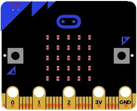
The Micro:bit is a small microcontroller board that acts as the central control unit for the fire detection system. It processes signals from the flame sensor, controls the buzzer, and turns the LED on or off based on the detection status.
KY-026 Flame Sensor:
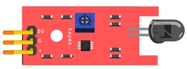
The KY-026 Flame Sensor is used to detect the presence of a flame by sensing the infrared (IR) radiation emitted by fire.
Buzzer
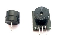
The buzzer is used as an audible alarm to alert users when a flame is detected.
LED
The LED provides a visual indicator for flame detection. It is an external light source used in conjunction with the buzzer for alerting users.
GPIO Card (Edge Connector Breakout Board)
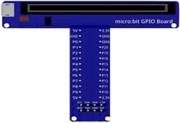
The GPIO card or edge connector breakout board is an adapter that makes it easier to access and connect the Micro:bit's I/O pins to external components like sensors and actuators.
Jumper Wires:
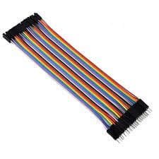
For making temporary connections and wiring between components.
Breadboard:
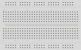
A breadboard is a useful tool for creating temporary electronic circuits. It allows you to connect components without soldering.
Mounting Micro:bit with KY-026 sensor, and Buzzer
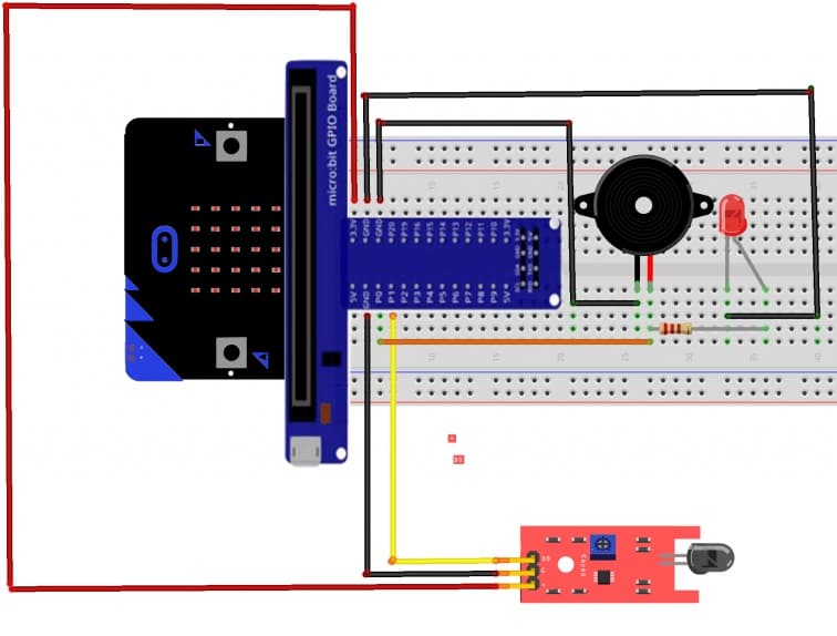
1- KY-026 Flame Sensor:
VCC → Micro:bit 3.3V (or external 5V supply).
GND → Micro:bit GND.
DO → Micro:bit P0.
Buzzer:
Positive (+) → Micro:bit P1.
Negative (-) → Micro:bit GND.
LED:
Anode (long leg) → Micro:bit P1 (via 220Ω resistor).
Cathode (short leg) → Micro:bit GND.
Program Micro:bit with Makecode
1- Open MakeCode at makecode.microbit.org.
2- Create a New Project.
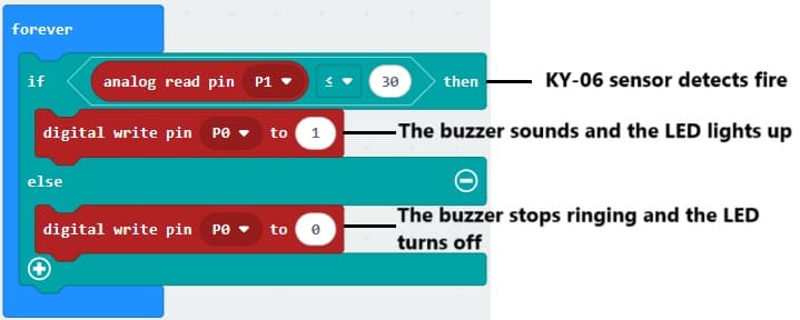
3- Add an if condition to check if the flame sensor's output is LOW (flame detected) using analog read pin P1:
Activate the buzzer and Turn on the LED using digital write pin P1 to 1.
4- Add an else condition for no flame detected:
Deactivate the buzzer Turn off the LED using digital write pin P1 to 0.
Here’s how the blocks should look in MakeCode:
