Micro:bit door security system
Tutorial plan
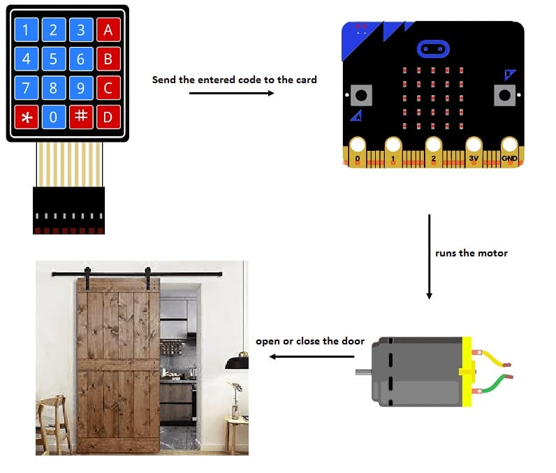
1- How does the Micro:bit board control door access ?
2- Necessary components
3- Wiring diagram of system
4- Makecode program for Micro:bit
How does the Micro:bit board control door access ?
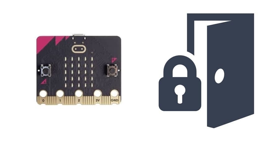
The Micro:bit board can control door access by working with a DC motor, a driver expansion board and a 4x4 keypad to create an electronic access control system. Here's a description of its functioning:
User Input: The user enters a passcode using the 4x4 keypad.
Validation:
1- If the passcode matches the stored code:
LCD displays "Access Granted."
The Micro:bit activates the motor driver to rotate the DC motor and unlock the door.
After a delay, the motor resets, locking the door again.
2- If the passcode is incorrect:
LCD displays "Access Denied."
The door remains locked.
System Reset: The system resets, ready for the next input.
Necessary components
Micro:bit Microcontroller:
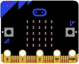
The Micro:bit serves as the central controller for the system.
It processes the passcode entered via the keypad and compares it with the stored passcode.
If the entered code is correct, the Micro:bit sends a signal to the motor driver to unlock the door.
If the code is incorrect, it displays an error message on the LCD and denies access.
4x4 Keypad:
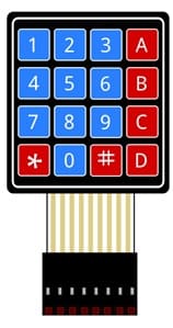
The 4x4 keypad acts as an input device for the user to enter a passcode.
The Micro:bit reads the keypresses from the keypad and compares the entered code to a pre-stored valid passcode.
Driver Expansion Board:
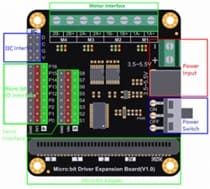
The driver expansion board acts as an interface between the Micro:bit and the DC motor.
It amplifies the low-power signals from the Micro:bit to control the DC motor, which requires higher power to operate.
It ensures the motor receives sufficient current and voltage without overloading the Micro:bit.
DC Motor (Door Control):

The DC motor physically moves the locking mechanism (e.g., slides a bolt or rotates a latch) to unlock or lock the door.
When the Micro:bit sends a signal to the driver expansion board, the motor either rotates to unlock the door or resets to lock it after a delay.
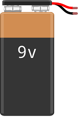
Power Source:
A battery pack or power supply provides sufficient voltage and current for the motor
Wiring diagram of system
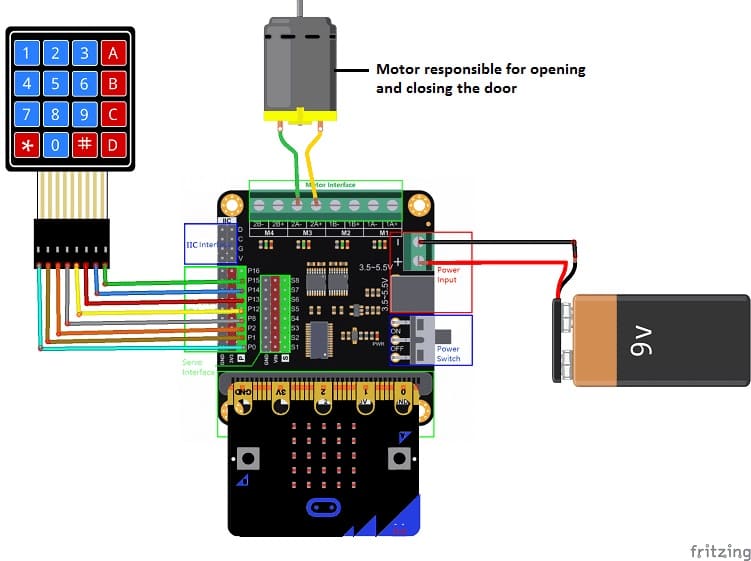
To carry out the assembly, we connect:
- the 8 keyboard outputs to the 8 Micro:bit pins (P0, P1, P2, P8, P12, P13, P14, P15)
- both motor terminals to 2 pin M3 of the Driver Expansion Board
Makecode program for Micro:bit
In MakeCode, the logic is implemented using blocks for easier programming.
Here is an example of program which allows the door to be opened or closed by the Micro:bit card.
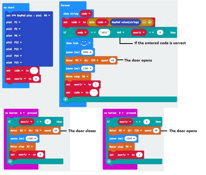
1- Define Keypad Inputs:
Create variables for the keypad rows and columns.
Use "on button press" or "pin pressed" blocks to detect keypresses.
Store the keypresses in a variable to form the passcode.
2- Validate Passcode:
Use an "if-then-else" block to check if the entered passcode matches the pre-stored passcode.
If it matches:
Display "Access Granted" on the LED matrix.
Activate the motor by sending a signal to the driver board.
If it doesn't match:
Display "Access Denied" on the LED matrix.
3- Control the Motor:
One signal to rotate the motor (unlock the door).
Another signal (after a delay) to reset the motor (lock the door again).
