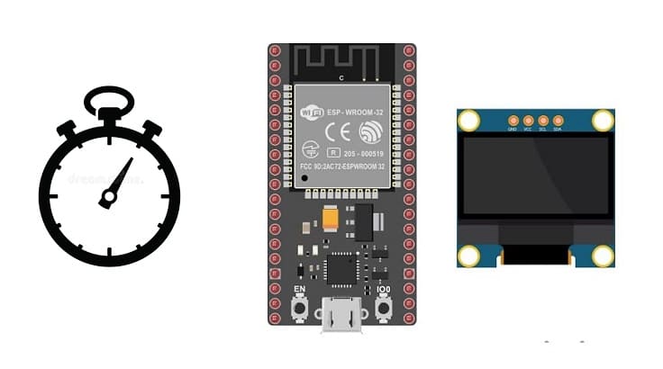
Making a chronometer with ESP32 board and SSD1306 display
Tutorial plan
1- Operation of the chronometer controlled by the ESP32 board
2- The components needed to build a chronometer controlled by the ESP32 board
3- Mounting the ESP32 board with the SSD1306 display and push buttons
4- Programming the ESP32 board with Micropyhton to display the chronometer on SSD1306 display
Operation of the chronometer controlled by the ESP32 board
A chronometer is a timekeeping device used to measure the amount of time elapsed between its activation and deactivation. It typically consists of a digital or analog display and buttons to start, stop, and reset the timer. chronometer functions are commonly used in sports, fitness activities, scientific experiments, and various timed events where precise timing is essential.
Using a chronometer with ESP32 board is a fun and educational project. You can create a simple chronometer using theESP32 board and some additional components like buttons and SSD1306 display.
The operation of the chronometer controlled by the ESP32 board with SSD1306 display and push buttons can be described as follows:
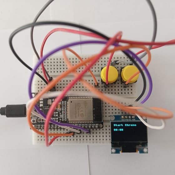
Initial Startup: When you power theESP32 board, the timer begins to display Press START on the SSD1306 display.
Start Button: By pressing the Start button, the chronometer starts measuring the time from 00:00 until you press the Stop button.
When the chronometer is running, the SSD1306 display shows the elapsed time in minutes and seconds, for example, 00:15 (15 seconds elapsed), 01:30 (1 minute and 30 seconds), etc.
Pressing the stop button again causes the chronometer to freeze, recording the time elapsed up to that point, without setting it to zero.
Reset Button: By pressing the reset button, the timer returns to 00:00, thereby resetting the elapsed time to zero, regardless of its previous state (running or stopped).
This operation allows you to control the chronometer using the push buttons: start to start measuring time, stop to freeze the current time and reset to reset the chronometer to zero. The SSD1306 display shows real-time elapsed time in minutes:seconds format while the chronometer is running.
The components needed to build a chronometer controlled by the ESP32 board
To build a chronometer controlled by an ESP32 board, you'll need several components to create the necessary functionalities. Here's a list of components required:
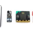
ESP32 board:
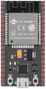
The ESP32 is a powerful microcontroller developed by Espressif Systems. It's renowned for its integrated Wi-Fi and Bluetooth capabilities, making it a popular choice for various IoT (Internet of Things) applications.
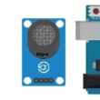
SSD1306 Display:
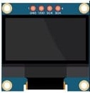
The SSD1306 display is a small OLED (Organic Light Emitting Diode) screen known for its use in various electronic projects. It's commonly employed for displaying information in DIY electronics, such as displaying text, graphics, or icons. The SSD1306 usually comes in resolutions like 128x64 pixels or 128x32 pixels and can be controlled by microcontrollers like ESP32 board.
Pushbuttons:
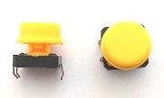
These will serve as controls for starting, stopping, and resetting the chronometer.
Breadboard:

A breadboard is a useful tool for creating temporary electronic circuits. It allows you to connect components without soldering.
Jumper Wires:

For making temporary connections and wiring between components.
These are the basic components required to build a chronometer using the ESP32 board. The specific values and quantities might vary based on your design preferences and the exact functionality you wish to implement.
Mounting the ESP32 board with the SSD1306 display and push buttons
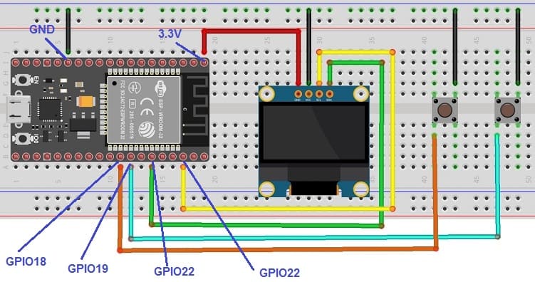
Mounting the ESP32 board with SSD1306 display and push buttons involves physically setting up these components on a breadboard or a prototyping board and wiring them together. Here's a step-by-step guide to mounting these components:
Mount the SSD1306 Display:
- Connect the GND pin of the SSD1306 display to the GND pin of the ESP32 board
- Connect the VCC pin of the SSD1306 display to the 3.3V pin of the ESP32 board
- Connect the SDA pin of the SSD1306 display to the GPIO 21 of the ESP32 board
- Connect the SCL pin of the SSD1306 display to the GPIO 22 of the ESP32 board
Connect Start Push Button:
- Connect the one of the legs of the push button to GPIO 19 of the ESP32 board
- Connect another pin of the push button to the GND pin of the ESP32 board
Connect Reset Push Button:
- Connect the one of the legs of the push button to GPIO 18 of the ESP32 board
- Connect another pin of the push button to the GND pin of the ESP32 board
Programming the ESP32 board with Micropyhton to display the chronometer on SSD1306 display
Ensure you have the Micropython firmware installed on your ESP32 and the necessary libraries (such as ssd1306.py) installed on your board before running this code. Also, adjust the SCL and SDA pins (Pin(22) and Pin(21)) according to the actual wiring of your ESP32.
This code initializes an SSD1306 display, starts a chronometer when executed, and displays the elapsed time on the OLED screen.
|
1 2 3 4 5 6 7 8 9 10 11 12 13 14 15 16 17 18 19 20 21 22 23 24 25 26 27 28 29 30 31 32 33 34 35 36 37 38 39 40 41 42 43 44 45 46 47 48 49 50 51 52 53 54 55 56 57 58 59 60 61 |
import machine from machine import Pin import time from machine import Pin, I2C import ssd1306 # Setup the SSD1306 display i2c = I2C(-1, scl=Pin(22), sda=Pin(21)) oled_width = 128 oled_height = 64 oled = ssd1306.SSD1306_I2C(oled_width, oled_height, i2c) # Set up the push buttons start_button= machine.Pin(19, machine.Pin.IN, machine.Pin.PULL_UP) reset_button = machine.Pin(18, machine.Pin.IN, machine.Pin.PULL_UP) start_state=0; reset_state=0; running=False; timer=0 second=0 minute=0 oled.text('Start Chrono', 0, 0) oled.text('00:00', 0, 20) oled.show() while True: #If you press the Start button if (start_button.value() == False): running = not running print("status:"+str(running)) if (running==False): oled.fill(0) <span class="hljs-comment"># Clear the screen</span> oled.text('Chrono stopped', 0, 0) # Display "Chrono stopped" oled.text(str(minute)+':'+str(second), 0, 20) # Display time oled.show() # Update the display time.sleep(0.5) #If you press the Reset button if (reset_button.value() == False): print("Reset") timer=0 second=0 minute=0 oled.fill(0) oled.text('Start Chrono', 0, 0) oled.text('00:00', 0, 20) oled.show() # Update the display time.sleep(0.5) running=False if (running): second += 1 time.sleep(0.01) if (second == 60): second = 0 minute += 1 if (minute == 60): minute = 0 oled.fill(0) oled.text('Chrono running', 0, 0) oled.text(str(minute)+':'+str(second), 0, 20) oled.show() |
0 comment
Leave a comment
Passion for robotics

Recent tutorials


Robotics workshop

Polpular tutorials


Making robots

Most commented tutorials


Robotic arm

Categories
Smart Home