Light up two LEDs connected to ESP32 by remote control
Tutorial plan
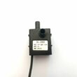
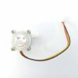
1- Introducing the KY-032 Infrared Sensor
2- The relationship between the KY-032 infrared sensor and a remote control
3- How to receive the ESP32 an infrared signal from the remote control using the KY-032 sensor?
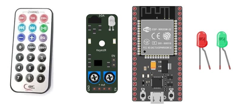
4- The components needed to use the KY-032 infrared sensor and two LEDs with the ESP32
5- Mounting the ESP32 with the KY-032 infrared sensor and two LEDs
6- Light up two LEDs by the remote control using the KY-032 infrared sensor and the ESP32 board with micropython
Introducing the KY-032 Infrared Sensor
The KY-032 Infrared Sensor is a module that is commonly used in electronics and robotics projects for detecting the presence of infrared signals. It is also known as an infrared obstacle avoidance sensor module. The module consists of an infrared emitter (LED) and an infrared receiver (phototransistor) placed side by side.
Here are some key features and characteristics of the KY-032 Infrared Sensor:
1- Detection Method: The sensor module detects infrared light by emitting a modulated infrared signal and measuring the reflection. When an object is present in front of the module, the infrared light emitted by the LED bounces off the object and is detected by the phototransistor.
2- Operating Voltage: The KY-032 module typically operates at a voltage range of 3.3V to 5V, making it compatible with most microcontrollers and development boards.
3- Digital Output: The module provides a digital output that can be easily interfaced with microcontrollers or other digital circuits. It produces a HIGH (logic 1) output when no obstacle is detected and a LOW (logic 0) output when an obstacle is detected within its detection range.
4- Adjustable Detection Range: The detection range of the KY-032 sensor can be adjusted using a potentiometer on the module. This allows you to fine-tune the sensitivity of the sensor according to your specific requirements.
5- Applications: The KY-032 Infrared Sensor can be used in various applications, including obstacle detection and avoidance in robotics, line following robots, proximity sensing, object detection, and security systems.
When using the KY-032 Infrared Sensor, it's important to keep in mind that it primarily detects the presence of objects based on their reflective properties rather than their distance. The effectiveness of the sensor can be affected by factors such as ambient light and the reflective properties of the objects being detected.
How to receive the ESP32 board an infrared signal from the remote control using the KY-032 sensor?
To receive an infrared signal from a remote control using an ESP32 board and the KY-032 sensor in MicroPython, you can follow these steps:
1- Hardware Setup: Connect the KY-032 sensor to the ESP32 board. The KY-032 module usually has three pins: VCC, GND, and OUT. Connect them as follows:
- VCC -> 3.3V (ESP32's 3V3 pin)
- GND -> GND (ESP32's GND pin)
- OUT -> GPIO 22 pin (any digital input pin on ESP32)
2- Install MicroPython: Make sure you have MicroPython installed on your ESP32 board. If you haven't done it yet, you can find the firmware and installation instructions on the official MicroPython website: https://micropython.org/download
3- Import ir_rx library
4- Write the MicroPython Code: Create a new Python file (e.g., infrared_receiver.py) and write the following code to initialize and read from the KY-032 sensor:
|
1 2 3 4 5 6 7 8 9 10 11 12 13 14 15 16 17 18 19 20 21 22 23 24 25 26 27 28 29 30 31 32 33 34 35 36 37 38 39 40 41 42 43 44 45 |
from machine import Pin from ir_rx import NEC_16 ir_key = { 0x45: 'POWER', 0x46: 'MODE', 0x47: 'MUTE', 0x44: 'PLAY', 0x40: 'PREV', 0x43: 'NEXT', 0x07: 'EQ', 0x15: 'MINUS', 0x09: 'PLUS', 0x16: '0', 0x19: 'REPEAT', 0x0D: 'USD', 0x0C: '1', 0x18: '2', 0x5E: '3', 0x08: '4', 0x1C: '5', 0x5A: '6', 0x42: '7', 0x52: '8', 0x4A: '9' } # Function to display received infrared codes def ir_callback(data, addr, ctrl): global ir_data global ir_addr if data > 0: ir_data = data ir_addr = addr #display actual buttons key print(ir_key[data]) # Set digital input pin for KY-032 sensor ir = NEC_16(Pin(22, Pin.IN), ir_callback) ir_data = 0 ir_addr = 0 while True: if ir_data > 0: ir_data = 0 |
The components needed to use the KY-032 infrared sensor and two LEDs with the ESP32 board
To use the KY-032 infrared sensor and two LEDs with the ESP32, you will need a few components and connections. Here's a list of the required items:
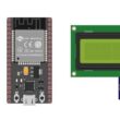
1- ESP32 board:
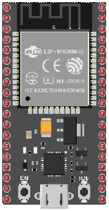
The ESP32 is a popular and powerful microcontroller developed by Espressif Systems. It is widely used in various IoT (Internet of Things) applications due to its versatility and robust capabilities.
The ESP32 is widely used in projects like smart home devices, wearables, robotics, environmental monitoring systems, industrial automation, and much more. Its versatility and excellent performance have made it a go-to choice for many IoT-related applications.
2- KY-032 Infrared Sensor:
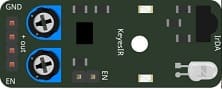
This sensor detects infrared signals and can be used to detect objects or receive signals from a remote control.
3- Two LEDs (Light Emitting Diode):
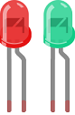
A Light Emitting Diode (LED) is a semiconductor device that emits light when an electric current passes through it. LEDs are widely used in various applications due to their efficiency, small size, and low power consumption.
4- Two resistors
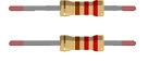
A resistor is an electrical component that is designed to have a specific resistance to the flow of electric current. It is one of the most fundamental and commonly used passive electronic components. Resistors are widely used in electronic circuits to control the amount of current flowing through a circuit, to limit current flow, and to divide voltages.
5- Breadboard:

A breadboard is a useful tool for creating temporary electronic circuits. It allows you to connect components without soldering.
6- Jumper wires:

These wires are used to make connections between the Micro:bit, KY-032 sensor, LED, and breadboard.
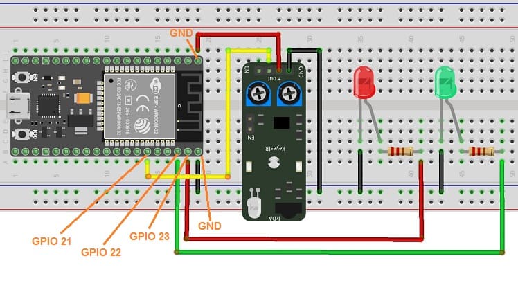
Mounting the ESP32 board with the KY-032 infrared sensor and two LEDs
Mounting the ESP32 board with the KY-032 infrared sensor and an LED is a straightforward process. Here's a step-by-step guide to help you set it up:
1- Connect the VCC pin of the KY-032 sensor to the 5V pin of the ESP32 board.
2- Connect the GND pin of the KY-032 sensor to the GND pin of the ESP32 board.
3- Connect the OUT pin of the KY-032 sensor to any digital input pin on the ESP32 (e.g., GPIO 21).
4- Connect the negative leg of the red LED to GND pin on the ESP32.
5- Connect the positive leg of the red LED to a current-limiting resistor, and then connect the other end of the resistor to GPIO 23 pin on the ESP32.
6- Connect the negative leg of the green LED to GND pin on the ESP32.
7- Connect the positive leg of the green LED to a current-limiting resistor, and then connect the other end of the resistor to GPIO 22 pin on the ESP32.
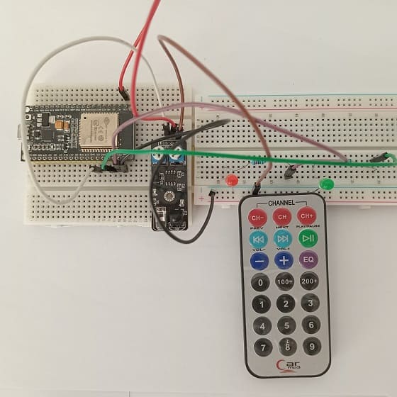
Light up two LEDs by the remote control using the KY-032 infrared sensor and the ESP32 board with micropython
To program the ESP32 board to receive data from the KY-032 infrared sensor and light up two LEDs using MicroPython, you'll need to follow these steps:
Step 1: Install MicroPython on ESP32 If you haven't installed MicroPython on your ESP32 board, you'll need to do that first. You can find the MicroPython firmware for ESP32 on the official MicroPython website (https://micropython.org/download/esp32/). Follow the instructions to flash the firmware onto your ESP32 board.
Step 2: Connect the Hardware Connect the KY-032 sensor and the two LEDs to the appropriate GPIO pins on the ESP32 board. Make sure to connect the VCC and GND pins of the sensor to the appropriate power and ground pins on the ESP32.
To light up two LEDs using the remote control and the KY-032 infrared sensor with an ESP32 board running MicroPython, you'll need to capture the IR codes from the remote control and then map those codes to specific actions, such as turning the two LEDs on and off. Here's a step-by-step guide to achieve this:
Step 3: Install Required Library You'll need to install the ir_rx library to work with the KY-032 infrared sensor. This library is compatible with the ESP32 and works with MicroPython. You can find the library and instructions on how to install it here: ir_rx
Step 4: Writing the MicroPython Code Next, you'll need to write the MicroPython code.
Here's a sample MicroPython code to read data from the KY-032 sensor and control the two LEDs based on its output:
|
1 2 3 4 5 6 7 8 9 10 11 12 13 14 15 16 17 18 19 20 21 22 23 24 25 26 27 28 29 30 31 32 33 34 35 36 37 |
import machine <span class="crayon-e">from </span><span class="crayon-e">ir_rx </span><span class="crayon-e">import </span><span class="crayon-e">NEC_16</span> # Define the GPIO pins for the sensor and two LEDs ir_sensor_pin = 21 # Connect KY-032 OUT pin to GPIO 21 red_led_pin = 23 # Connect red LED to GPIO 23 green_led_pin = 22 # Connect green LED to GPIO 22 # Set up the LED pin ir_sensor = machine.Pin(ir_sensor_pin, machine.Pin.IN) red_led = machine.Pin(red_led_pin, machine.Pin.OUT) green_led = machine.Pin(green_led_pin, machine.Pin.OUT) # Function to capture and map IR codes to LED actions def ir_callback(data, addr, ctrl): global ir_data global ir_addr if data > 0: ir_data = data ir_addr = addr print('Data {:02x} Addr {:04x}'.format(data, addr)) # Create the IR receiver object ir = NEC_16(ir_sensor, ir_callback) ir_data = 0 ir_addr = 0 # Main loop while True: if ir_data > 0: if ir_data==0x0C: # if you press button 1 on the remote control red_led.value(1) # Turn on the red LED green_led.value(1) # Turn on the green LED if ir_data==0x18: # if you press button 2 on the remote control red_led.value(0) # Turn off the red LED green_led.value(0) # Turn off the green LED ir_data = 0 |
Step 5: Transfer the Code to ESP32 Transfer the updated MicroPython code, which includes IR code mapping, to your ESP32 board using ampy or Thonny IDE (as described in the previous answer).
Step 6: Test Now, when you use the specific buttons on the remote control associated with the mapped IR codes, the two LEDs should turn on and off accordingly.
0 comment
Leave a comment
Passion for robotics

Recent tutorials


Robotics workshop

Polpular tutorials


Making robots

Most commented tutorials
Robotic arm

Categories
Smart Home