Light up three LEDs connected to Arduino UNO using the push buttons
Tutorial plan
1- Role of the push button in robotics
2-The components necessary to control three LEDs by push buttons through the Arduino UNO board
3-Mounting the Arduino UNO board with three LEDs and push buttons
4-Programming the Arduino UNO board to turn on three LEDs using the push button
Role of the push button in robotics
Push buttons can play a significant role in robotics by serving as a means of human interaction and control in various ways:
Start/Stop Control: Push buttons are often used to start and stop robotic systems. For example, a start button can initiate the robot's operation, and a stop button can halt it in case of an emergency or to end a task.
Emergency Stop (E-Stop): Emergency stop buttons are critical safety features in robotics. They provide an immediate and easily accessible way to shut down the robot in case of a malfunction or a hazardous situation. This is crucial for ensuring the safety of both the robot and the people working around it.
Mode Selection: In more complex robotic systems, push buttons can be used to select different operational modes, such as autonomous mode, manual control mode, or specific task modes. Users can switch between these modes using buttons.
User Interface: Push buttons can be used to provide a simple user interface for users to interact with the robot. They can trigger specific actions or functions, like moving an arm, activating a gripper, or changing the robot's behavior.
Teaching and Programming: Push buttons can be used in a teaching or programming mode, where operators can manually move robot arms or other components to demonstrate desired motions or trajectories. This information can be recorded and later reproduced by the robot.
Limit or Home Switches: Push buttons can be used as limit switches or home switches in robotics. They help the robot establish reference points or boundaries for its movement, ensuring accuracy and safety.
Calibration and Configuration: Push buttons can be used for calibrating sensors, configuring parameters, or setting up the robot's initial conditions. They can be part of a setup process to ensure that the robot operates as intended.
Reset or Clear Function: Push buttons can be used to reset the robot's state, clear error conditions, or restart specific tasks. They can help recover from unexpected situations.
User Feedback: Some push buttons may include indicator lights or displays to provide feedback to the user, such as the current mode, status, or system health.
Push buttons, when combined with microcontrollers and control systems, offer a convenient way for humans to interact with and control robots, whether in industrial automation, research, or various other applications. Their design and functionality can vary based on the specific needs of the robotic system and the safety requirements associated with it.
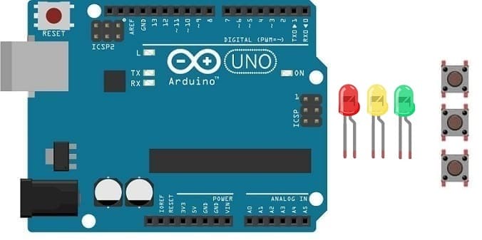
The components necessary to control three LEDs by push buttons through the Arduino UNO board
To control three LEDs using an Arduino UNO and push buttons, you will need the following components:
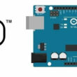
Arduino UNO:
The Arduino UNO is a microcontroller board that serves as the brain of your project. It provides the necessary I/O pins and processing power to control the RGB LED module.
LEDs :
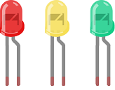
LED stands for "Light Emitting Diode." It is a semiconductor device that emits light when an electric current passes through it.
Push button:
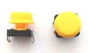
A push button, also known as a momentary switch or tactile switch, is a simple yet commonly used electromechanical component in electronics. It is designed to make or break an electrical connection temporarily when pressed or released.
Resistance
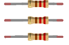
In the context of electronics and electrical circuits, a resistance refers to a passive two-terminal electrical component that restricts the flow of electric current. It is typically measured in ohms (Ω).
Breadboard:

A breadboard is a prototyping board that allows you to build circuits without soldering. It provides a convenient way to connect the components together.
Jumper Wires:

You'll need jumper wires to make connections between the Arduino UNO, three LED , push buttons and breadboard.
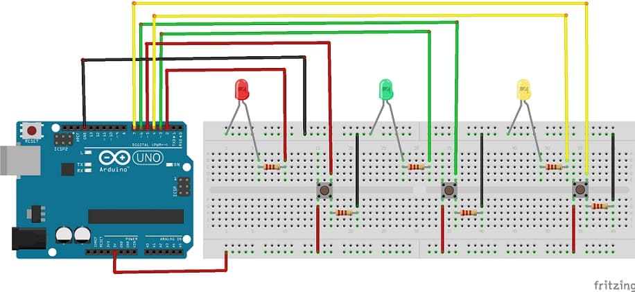
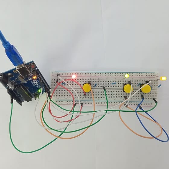
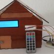
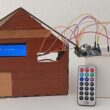
Mounting the Arduino UNO board with three LEDs and push button
Once you have the necessary components, you can proceed with the following steps to control three LEDs with push buttons:
Red LED :
1- Connect the anode (longer lead) of the red LED to a current-limiting resistor (e.g., 220-330 ohms).
2- Connect the other end of the resistor to one of the Arduino Uno's digital output pins (pin 2).
3- Connect the cathode (shorter lead) of the red LED to the ground (GND) on the Arduino Uno.
Green LED :
1- Connect the anode (longer lead) of the green LED to a current-limiting resistor (e.g., 220-330 ohms).
2- Connect the other end of the resistor to one of the Arduino Uno's digital output pins (pin 3).
3- Connect the cathode (shorter lead) of the green LED to the ground (GND) on the Arduino Uno.
Yellow LED :
1- Connect the anode (longer lead) of the yellow LED to a current-limiting resistor (e.g., 220-330 ohms).
2- Connect the other end of the resistor to one of the Arduino Uno's digital output pins (pin 4).
3- Connect the cathode (shorter lead) of the yellow LED to the ground (GND) on the Arduino Uno.
Push button 1:
1- Connect one leg of the push button to pin 5 of the Arduino.
2- Connect another leg of the push button to the 5V pin of the Arduino.
3- Place a 10k Ohm resistor between the third leg of the push button and the GND pin of the Arduino.
Push button 2:
1- Connect one leg of the push button to pin 6 of the Arduino.
2- Connect another leg of the push button to the 5V pin of the Arduino.
3- Place a 10k Ohm resistor between the third leg of the push button and the GND pin of the Arduino.
Push button 3:
1- Connect one leg of the push button to pin 7 of the Arduino.
2- Connect another leg of the push button to the 5V pin of the Arduino.
3- Place a 10k Ohm resistor between the third leg of the push button and the GND pin of the Arduino.
Programming the Arduino UNO board to turn on three LEDs using the push buttons
Here's an example Arduino sketch to get you started. This code will turn on one LED when you press one button and turn on the other LED when you press the other button. It will also ensure that the LEDs stay on until you release the button.
|
1 2 3 4 5 6 7 8 9 10 11 12 13 14 15 16 17 18 19 20 21 22 23 24 25 26 27 28 29 30 31 32 33 34 35 36 37 38 39 40 41 42 43 44 45 46 47 48 49 50 51 52 53 54 55 56 57 58 59 60 61 62 63 64 65 66 67 68 69 70 71 |
#define Red_PIN 2 // the number of pin for red LED #define Red_BUTTON_PIN 5 // the number of the pushbutton pin to light red LED byte RedlastButtonState = LOW; // to keep the state of the first button and the red LED byte RedledState = LOW; // to keep the state of the first button and the red LED byte GreenlastButtonState = LOW; // to keep the state of the button and the Green LED byte GreenledState = LOW; // to keep the state of the button and the Green LED byte YellowlastButtonState = LOW; // to keep the state of the button and the yellow LED byte YellowledState = LOW; // to keep the state of the button and the Yellow LED unsigned long debounceDuration = 50; // millis unsigned long lastTimeRedButtonStateChanged = 0; unsigned long lastTimeGreenButtonStateChanged = 0; unsigned long lastTimeYellowButtonStateChanged = 0; void setup() { // initialize the pin as an output: pinMode(Red_PIN, OUTPUT); pinMode(Green_PIN, OUTPUT); pinMode(Yellow_PIN, OUTPUT); // initialize the pushbutton pin as an input: pinMode(Red_BUTTON_PIN, INPUT); pinMode(Green_BUTTON_PIN, INPUT); pinMode(Yellow_BUTTON_PIN, INPUT); } void loop() { // to turn the red LED on or off using the push button if (millis() - lastTimeRedButtonStateChanged > debounceDuration) //start the button/LED functionality if enough time has passed since the last time the button’s state was changed { byte RedbuttonState = digitalRead(Red_BUTTON_PIN); // the pushbutton is pressed if (RedbuttonState != RedlastButtonState) { lastTimeRedButtonStateChanged = millis(); RedlastButtonState = RedbuttonState; if (RedbuttonState == LOW) { RedledState = (RedledState == HIGH) ? LOW: HIGH; // Toggle the state of the RGB LED when the button has been released digitalWrite(Red_PIN, RedledState); // turn the red color on or off depending on the state of the LED } } } // to turn the green LED on or off using the push button if (millis() - lastTimeGreenButtonStateChanged > debounceDuration) { byte GreenbuttonState = digitalRead(Green_BUTTON_PIN); if (GreenbuttonState != GreenlastButtonState) { lastTimeGreenButtonStateChanged = millis(); GreenlastButtonState = GreenbuttonState; if (GreenbuttonState == LOW) { GreenledState = (GreenledState == HIGH) ? LOW: HIGH; digitalWrite(Green_PIN, GreenledState); } } } // to turn the yellow LED on or off using the push button if (millis() - lastTimeYellowButtonStateChanged > debounceDuration) { byte YellowbuttonState = digitalRead(Yellow_BUTTON_PIN); if (YellowbuttonState != YellowlastButtonState) { lastTimeYellowButtonStateChanged = millis(); YellowlastButtonState = YellowbuttonState; if (YellowbuttonState == LOW) { YellowledState = (YellowledState == HIGH) ? LOW: HIGH; digitalWrite(Yellow_PIN,YellowledState); } } } } |
Upload the Code:
Compile the code by clicking the checkmark icon in the Arduino IDE.
Upload the code to your Arduino Uno board by clicking the right arrow icon.
Testing:
Once the code is uploaded, press the push buttons to test the LEDs. They should turn on when you press the corresponding button and turn off when you release it.
That's it! You now have a basic Arduino program that controls three LEDs using push buttons. You can expand and customize this project to suit your needs.
0 comment
Leave a comment
Passion for robotics

Recent tutorials
Robotics workshop

Polpular tutorials


Making robots

Most commented tutorials
Robotic arm

Categories
Smart Home