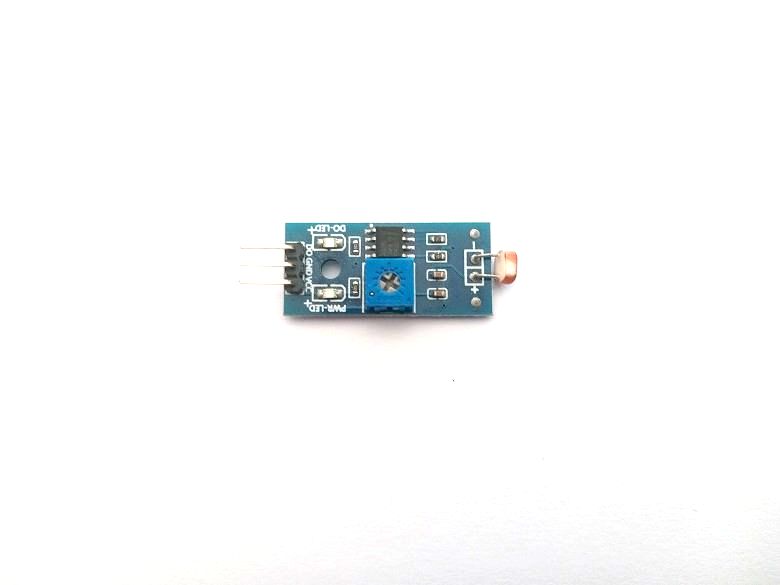
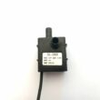
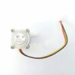
LDR sensor module
What is an LDR sensor module ?
An LDR (Light Dependent Resistor) sensor module is a type of electronic sensor that detects light intensity. It works by changing its resistance based on the amount of light falling on its surface. LDRs are also known as photoresistors or photocells.
An LDR sensor module typically consists of an LDR, an amplifier circuit, and a potentiometer to adjust the sensitivity of the module. The module usually has three pins: VCC (positive power supply), GND (ground), and an analog output pin. The analog output pin provides a voltage value that corresponds to the light intensity detected by the LDR.
LDR sensor modules are commonly used in various applications, such as light-activated switches, streetlights, and automatic plant watering systems. They are also used in robotics to detect light sources or track the position of the sun.
To use an LDR sensor module, you'll need to connect it to a microcontroller or other electronic device that can read the analog output value from the module. You'll also need to calibrate the LDR module to map the analog output voltage to a corresponding light intensity value. Once calibrated, you can use the LDR module to measure the light intensity in the surrounding environment and trigger actions or outputs based on the measured value.
The pins of the LDR sensor module
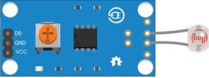
The LDR sensor module usually comes with three pins which are:
VCC pin: This pin is connected to the positive power source (5V or 3.3V) of the Arduino development board or microcontroller.
GND pin: This pin is connected to the negative power source (GND) of the Arduino development board or microcontroller.
Signal Pin (DO): This pin is connected to one of the analog ports on the Arduino development board or microcontroller. This pin is used to measure the resistance of the LDR which varies depending on the amount of light available.
It is important to note that the pin names and functions may vary depending on the manufacturer and model of the LDR sensor module. It is therefore recommended to consult the documentation provided by the manufacturer for more details on the connection and use of the module.
How to use LDR sensor module by microcontroller ?
To use an LDR (Light Dependent Resistor) sensor module with a microcontroller, you'll need to follow these steps:
1- Connect the LDR sensor module to your microcontroller: Most LDR modules come with three pins: VCC (positive power supply), GND (ground), and an analog output pin. Connect the VCC and GND pins of the module to the appropriate power and ground pins of the microcontroller (e.g., 5V and GND pins on an Arduino board). Connect the analog output pin of the LDR module to one of the analog input pins of the microcontroller.
2- Code your microcontroller to read the analog input: Depending on your microcontroller board and programming language, you'll need to use the appropriate function or library to read the analog input value from the LDR module. For example, on an Arduino board, you can use the analogRead() function to read the voltage value on the analog input pin.
3- Calibrate the LDR sensor module: Before you can use the LDR module to measure light intensity, you'll need to calibrate it to map the analog input voltage to a corresponding light intensity value. This can be done by placing the LDR module under different light conditions (e.g., bright sunlight, indoor lighting, darkness) and recording the analog input values. You can then use these values to create a lookup table or formula to convert the analog input voltage to a light intensity value.
4- Use the LDR sensor module to measure light intensity: Once the LDR module is calibrated, you can use it to measure the light intensity in the surrounding environment. Depending on your application, you can use the measured light intensity value to trigger an action or output (e.g., turn on a light, adjust the brightness of a display, etc.).
Here's some sample code in Arduino IDE to read the analog input from an LDR module:
|
1 2 3 4 5 6 7 8 9 10 11 12 |
int LDR_PIN = A0; // Analog input pin for LDR module void setup() { Serial.begin(9600); // Initialize serial communication } void loop() { int sensorValue = analogRead(LDR_PIN); // Read analog input from LDR module Serial.print("LDR sensor value: "); Serial.println(sensorValue); // Print sensor value to serial monitor delay(1000); // Wait for 1 second before reading again } |
Note that this code only reads the analog input from the LDR module and prints it to the serial monitor. You'll need to calibrate the LDR module and adjust the code accordingly to map the analog input to a light intensity value.
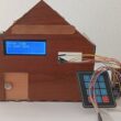
Role of LDR sensor module in automatic lighting system
In an automatic lighting system, an LDR (Light Dependent Resistor) sensor module plays a crucial role in detecting the level of ambient light in the environment and triggering the lighting system to turn on or off accordingly.
The LDR sensor module detects the light intensity in the surrounding environment and provides an analog voltage output that corresponds to the detected light intensity. This output voltage can be read by a microcontroller or other electronic device, which can then use it to determine whether the lighting system needs to be turned on or off.
For example, if the ambient light level falls below a certain threshold, the microcontroller can use the analog output value from the LDR module to determine that it is dark and turn on the lighting system. Conversely, if the ambient light level rises above a certain threshold, the microcontroller can use the analog output value to determine that it is light and turn off the lighting system.
By using an LDR sensor module in an automatic lighting system, the system can adjust to changes in ambient light level and ensure that the lighting is turned on only when needed. This can help save energy and reduce costs, as well as provide convenience and safety for users.
Role of the LDR sensor module in robotics
In robotics, an LDR (Light Dependent Resistor) sensor module is often used to detect the intensity of light in the environment and enable the robot to perform various tasks or behaviors.
Here are some common roles of an LDR sensor module in robotics:
Light tracking: An LDR sensor module can be used to track a light source, such as the sun or a flashlight. By using the output value from the LDR module, a robot can orient itself towards the light source and follow it.
Obstacle detection: An LDR sensor module can also be used to detect obstacles in the path of the robot. By comparing the output value from multiple LDR modules positioned at different angles, a robot can determine the location and shape of an obstacle and avoid it.
Line following: An LDR sensor module can be used to follow a line on the ground, which is commonly used in robotics competitions such as line following contests. By using multiple LDR modules positioned in a line, a robot can detect the contrast between the line and the background and follow the line accordingly.
Light-sensitive behavior: An LDR sensor module can also be used to enable a robot to exhibit light-sensitive behavior, such as turning towards a light source or avoiding bright light. By using the output value from the LDR module, a robot can determine the intensity of the light and adjust its behavior accordingly.
0 comment
Leave a comment
Passion for robotics

Recent tutorials
Robotics workshop

Polpular tutorials


Making robots

Most commented tutorials
Robotic arm

Categories
Smart Home