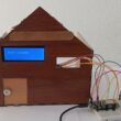
Gas alarm system based on Micro:bit board, MQ-4 sensor and LCD screen
Tutorial plan
Introduction
1- How the gas alarm system ordered by Micro:bit works ?
2- Mounting Micro:bit with MQ-4 sensor, LED, Buzzer and LCD screen
3- Program Micro:bit with Makecode to control the system
Introduction
A gas alarm system is a safety device designed to detect the presence of potentially harmful gases in an environment, such as carbon monoxide (CO), natural gas, propane, methane, or other combustible gases. These systems are commonly used in homes, commercial buildings, industrial facilities, and other locations where gas leaks could pose a threat to health and safety.
Here's how a typical gas alarm system works:
1- Gas Sensors: Gas alarm systems contain sensors that are capable of detecting specific types of gases. These sensors continuously monitor the air for the presence of gases, and when they detect a gas at a certain concentration level, they trigger an alarm.
2- Alarm Devices: When a gas is detected, the system activates alarm devices such as sirens, strobe lights, or audible alerts to warn occupants of the building about the potential danger. These alarms are usually loud and conspicuous to ensure they can be easily heard or seen.
3- Monitoring and Notification: In some cases, gas alarm systems are connected to monitoring services that can provide remote monitoring and notifications. This allows for immediate response in case of a gas leak, even if no one is present at the location where the alarm is installed.
4- Integration with Building Systems: Advanced gas alarm systems may be integrated with other building systems, such as ventilation systems or shut-off valves for gas lines. This integration allows for automated responses to gas leaks, such as activating ventilation to remove the gas from the building or shutting off the gas supply to prevent further leaks.
5- Maintenance and Testing: Regular maintenance and testing of gas alarm systems are essential to ensure their proper functioning. This includes periodic calibration of sensors, testing of alarm devices, and replacing batteries or other components as needed.
Overall, gas alarm systems play a crucial role in preventing accidents and protecting occupants from the dangers associated with gas leaks. They provide early warning of potential hazards, allowing people to take appropriate actions to mitigate the risks and ensure their safety.
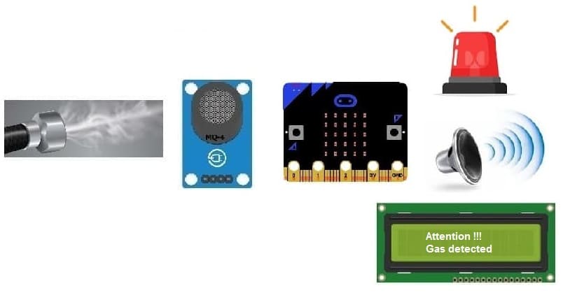
How the gas alarm system ordered by Micro:bit works ?
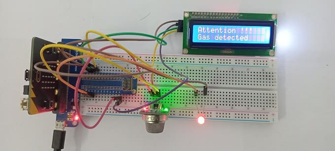
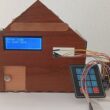
A gas alarm system based on a Micro:bit, MQ-Q-4 sensor, LCD screen, LED, and buzzer can be designed to detect the presence of certain gases in the environment and alert the user accordingly. Here's how such a system could work:
1- Hardware Setup:
Micro:bit:

This is the central control unit that will gather data from the sensor and control the display and alerts.
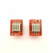
The GPIO expansion card for the Micro:bit card

The GPIO expansion board for the Micro:bit board expands the capabilities of the Micro:bit board by adding more input/output (GPIO) pins and additional functionality.
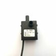
MQ-Q-4 Sensor:
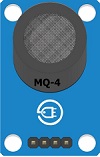
This gas sensor is capable of detecting various gases, including methane, butane, propane, and alcohol vapor.
LCD Screen:

Used to display relevant information such as gas concentration levels and warning messages.
LED:
![]()
This can be used as a visual indicator to signal the presence of gas.
Buzzer of Micro:bit:
This can be used as an audible alarm to alert the user when gas is detected.
Jumper Wires:

For making temporary connections and wiring between components.
Breadboard:

A breadboard is a useful tool for creating temporary electronic circuits. It allows you to connect components without soldering.
2- Connection:
Connect the MQ-Q-4 sensor to the Micro:bit using appropriate connections (e.g., analog or digital pins).
Connect the LCD screen to the Micro:bit using the available pins (typically, using I2C communication).
Connect the LED to the Micro:bit's GPIO pins.
3- Programming:
1- Write code for the Micro:bit to read data from the MQ-Q-4 sensor.
2- Analyze the sensor data to detect the presence and concentration of gas.
3- Display relevant information on the LCD screen, such as the type of gas detected and its concentration level.
4- Activate the LED to provide a visual indication when gas is detected.
5- Activate the buzzer to provide an audible alarm when gas concentration exceeds a certain threshold, indicating a potential hazard.
4- Operation:
1- The system continuously monitors the environment for the presence of gas.
2- When gas is detected, the Micro:bit processes the sensor data and triggers appropriate actions.
3- If the concentration of gas exceeds a predefined threshold, the buzzer is activated to alert the user.
4- The LCD screen displays information about the detected gas and its concentration level, providing additional feedback to the user.
5- The LED can also be used as an additional visual indicator to complement the LCD display and the buzzer alarm.
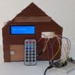
Mounting Micro:bit with MQ-4 sensor, LED, Buzzer and LCD screen
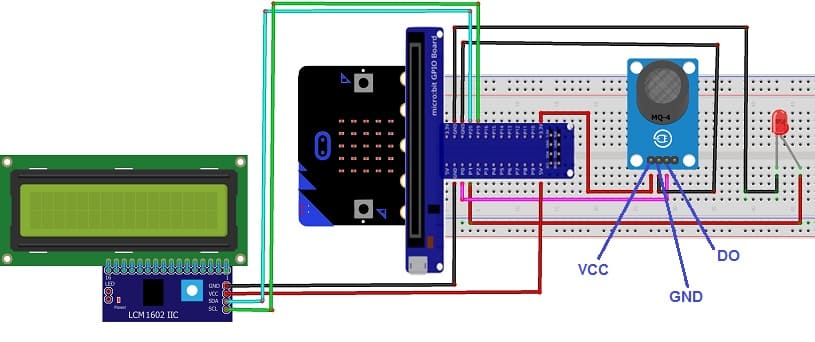
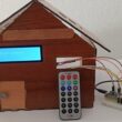
Attaching the MQ-4 sensor :
- Connect the VCC pin of the MQ-4 sensor to the 5V pin of the GPIO board
- Connect the GND pin of the MQ-4 sensor to the GND pin of the Micro:bit board
- Connect the DO pin of the MQ-4 sensor to P0 pin of the Micro:bit board
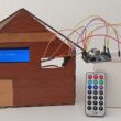
Attaching the red LED :
- Connect the negative terminal (cathode) of LED to the ground (GND) of the Micro:bit board.
- Connect the positive terminal (cathode) of LED to P1 pin of the Micro:bit board.
Attaching the LCD I2C 1602 Display :
- Connect the SDA (data line) of the LCD I2C 1602 display to P20 pin of Micro:bit board.
- Connect the SCL (clock line) of the LCD I2C 1602 display to P19 pin of Micro:bit board.
- Connect the VCC pin of the LCD I2C 1602 display to the 5V pin of GPIO board.
- Connect the GND pin of the LCD I2C 1602 display to GND pin of Micro:bit board.
Program Micro:bit with Makecode to control the system
To program the Micro:bit to control the gas alarm system, you can follow these steps:
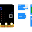
1- Open MakeCode Editor: Go to the MakeCode website (https://makecode.microbit.org/) and create a new project.
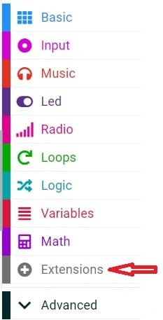
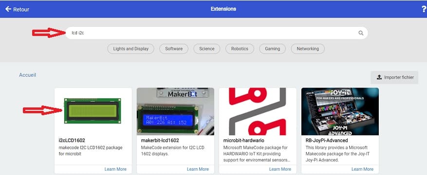
2- Add LCD Extension: Click on the "Advanced" menu, then select "Extensions." Search for "LCD" and add the extension that allows you to use the LCD screen with the Micro:bit.
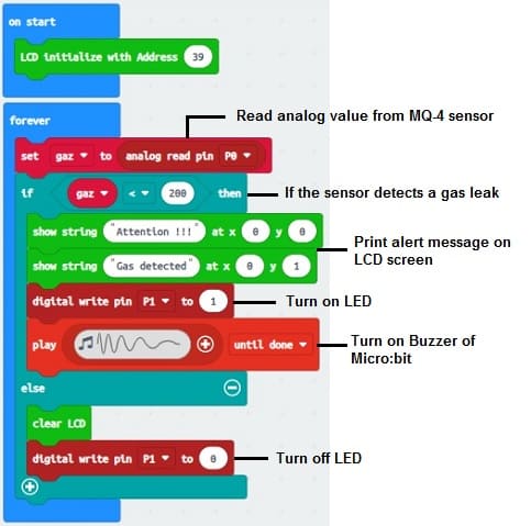
3- Below is a simple program for the gas alarm system based on the Micro:bit board :
Please note the following:
1- Ensure that you've added the necessary extensions for the LCD and buzzer support in the MakeCode editor.
2- Adjust the pins used for the MQ-Q-4 sensor, buzzer, and LED according to your setup.
3- Calibrate the gas threshold based on the sensitivity of your sensor and the acceptable gas concentration levels.
4- This program continuously reads the gas concentration from the sensor, displays it on the LCD screen, and activates the buzzer and LED if the concentration exceeds the specified threshold.
You can further enhance this program by adding features such as calibration routines, user interface enhancements, and additional safety checks as needed.
0 comment
Leave a comment
Passion for robotics

Recent tutorials
Robotics workshop

Polpular tutorials


Making robots

Most commented tutorials
Robotic arm

Categories
Smart Home