ESP32 Door Control System Using a Push Button
Tutorial plan
1- How Open a door with ESP32 and push button ?
2- Required Components
3- Circuit Connections of system
4- Micropython program to control the door
How Open a door with ESP32 and push button ?
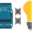
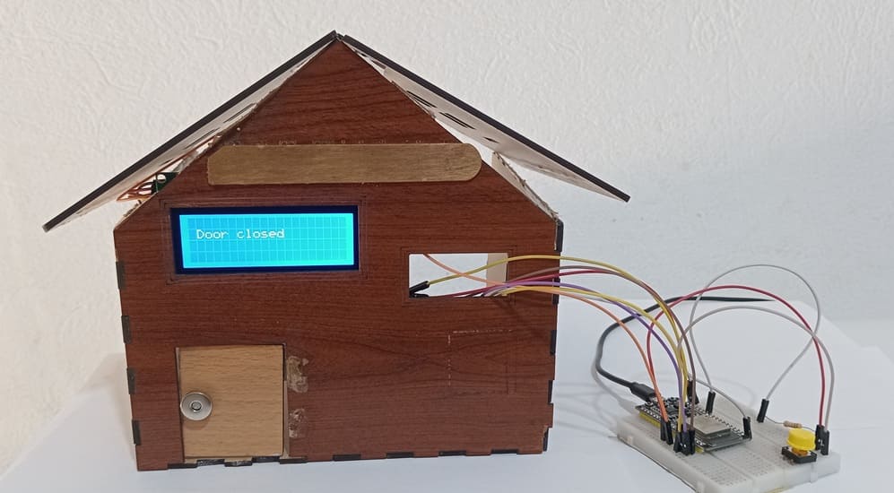
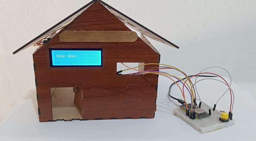
This project allows a user to control the opening and closing of a door using a simple push button. The ESP32 microcontroller handles the logic, a servo motor performs the mechanical door movement, and an I2C LCD display provides real-time visual feedback. This setup simulates an automated door mechanism, ideal for educational or prototype smart home applications.
How It Works (Functioning Step-by-Step):
1- System Initialization:
- When the ESP32 is powered on, it initializes all components.
- The LCD I2C display shows a welcome message (e.g., “System Ready” or “Door Closed”).
2- Idle State (Door Closed):
- The servo motor is set to its “closed” position (e.g., 90°, depending on how the door mechanism is designed).
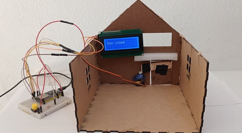
- The LCD displays: Door Closed.
3- Button Press Detection:
- The ESP32 constantly checks for a signal from the push button.
4- Opening the Door:
- When the button is pressed, the ESP32 triggers the door to open.
- The servo motor rotates to its “open” position (e.g., 20°).
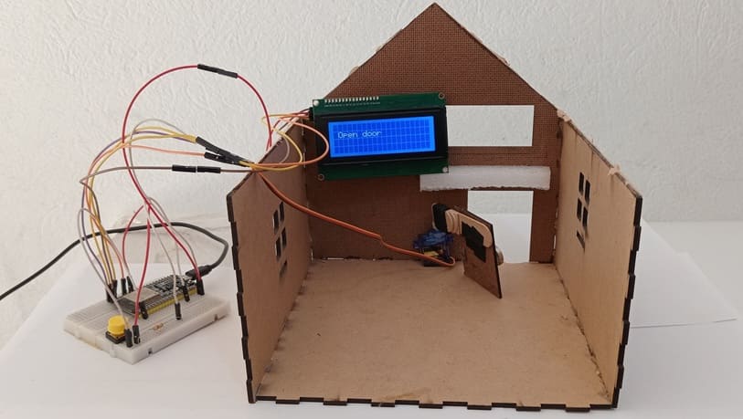
- The LCD updates to show: Opening... followed by Door Open.
5- Closing the Door Automatically:
- When the button is pressed again, the ESP32 triggers the door to close.
- the servo motor moves back to the “closed” position.
- The LCD displays: Closing... then Door Closed.
Required Components
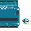
ESP32 Card
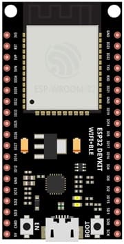
The ESP32 card acts as the brain of the system, controlling all inputs and outputs.
Push Button
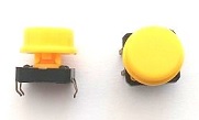
The push Button is used by the user to trigger the opening or closing of the door.
LCD I2C Display
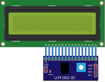
The LCD I2C Display Shows the current status of the door (e.g., "Door Closed", "Opening...", "Door Open", etc.).
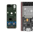
Servo Motor

The servo motor opens and closes the door by rotating to a specific angle.
10kΩ Resistor (Pull-Down Resistor)
![]()
A 10kΩ resistor is used to stabilize the push button input.
Breadboard

The Breadboard Connects components like the servo motor, LCD screen, and ESP32.
Wires and Jumpers
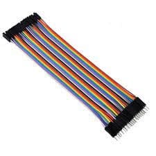
Ensure proper routing of power, ground, and data signals.
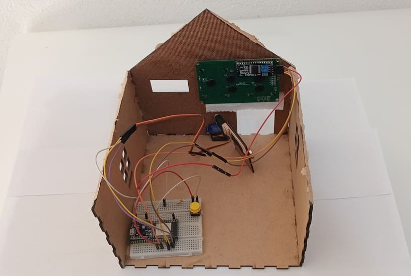
Wooden house prototype
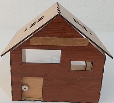
- Represents a real-life house model with a door that opens and closes.
- The servo motor is mounted inside the house, controlling the door movement.
- The LCD screen is attached to the exterior for status display.
Circuit Connections of system
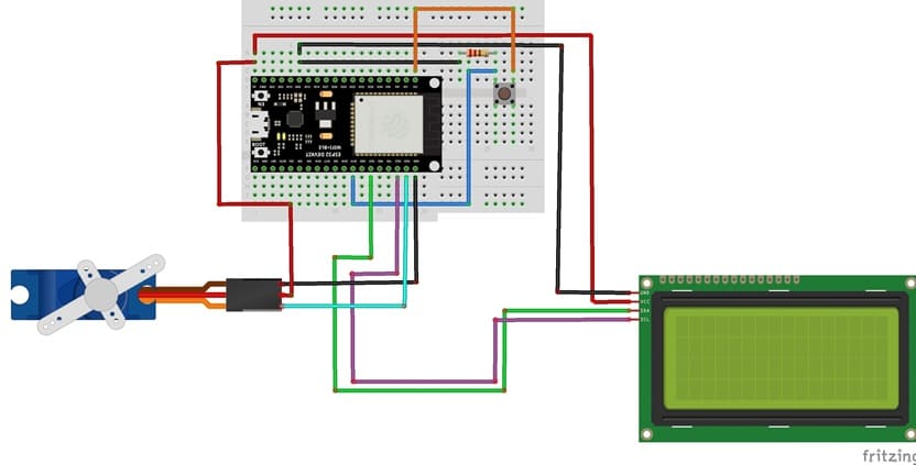
Connection of I2C LCD display
LCD I2C Pin | ESP32 pin |
VCC | 5 volt |
GND | GND |
SDA | GPIO 21 |
SCL | GPIO 22 |
Connection of servo motor
Servo motor | ESP32 |
Brown wire (-) | GND |
Red wire (+) | 5V |
Yellow wire (Signal) | GPIO 23 |
Connection of push button
- Connect a leg of button between 10kΩ Resistor and GND pin of ESP32
- Connect the same leg of button to GPIO 19 of ESP32
- Connect another leg of button to 3V3 pin of ESP32
Micropython program to control the door
Before running the code, install the necessary libraries:
- Servo (for servo motor)
- i2c_lcd and lcd_api for I2C LCD screen
|
1 2 3 4 5 6 7 8 9 10 11 12 13 14 15 16 17 18 19 20 21 22 23 24 25 26 27 28 29 30 31 32 33 34 35 36 37 38 39 40 41 42 43 44 45 46 47 48 49 50 51 52 53 54 55 56 |
import machine from machine import Pin, SoftI2C from time import sleep from servo import Servo from lcd_api import LcdApi from i2c_lcd import I2cLcd # --- I2C LCD Setup --- I2C_ADDR = 0x27 totalRows = 4 totalColumns = 20 i2c = SoftI2C(scl=Pin(22), sda=Pin(21), freq=10000) #initializing the I2C method for ESP32 lcd = I2cLcd(i2c, I2C_ADDR, totalRows, totalColumns) # --- Push Button Setup --- push_button = Pin(19, Pin.IN) # --- Servo Setup --- motor=Servo(pin=23) motor.move(90) position_door=90 lcd.clear() lcd.move_to(1,1) lcd.putstr("Door closed") # display door closed on LCD I2C display while True: if push_button.value()==1 : # If button is pressed if position_door==90: # if the door is closed lcd.clear() lcd.move_to(1,1) lcd.putstr("The door opens") for i in range(91,19,-1): motor.move(i) # rotate the servo motor to open the door sleep(0.1) position_door=20 lcd.clear() lcd.move_to(1,1) lcd.putstr("Open door") elif position_door==20: # if the door is open lcd.clear() lcd.move_to(1,1) lcd.putstr("The door closes") for i in range(20,91): motor.move(i) # rotate the servo motor to close the door sleep(0.1) position_door=90 lcd.clear() lcd.move_to(1,1) lcd.putstr("Door closed") |
0 comment
Leave a comment
Passion for robotics

Recent tutorials
Robotics workshop

Polpular tutorials


Making robots

Most commented tutorials


Robotic arm

Categories
Smart Home