Role of LEDs in robotics
LEDs (Light-Emitting Diodes) play several important roles in robotics. Here are a few key roles of LEDs in robotics:
- Indication and Status Display: LEDs are commonly used in robotics to indicate the status of different components or processes. For example, they can be used to indicate when a robot is powered on, when it is charging, or when it is in a specific mode of operation. LEDs provide a visual feedback mechanism for users or operators to understand the robot's current state.
- Navigation and Obstacle Detection: In robotic systems that operate in environments with low light or limited visibility, LEDs can be used for navigation and obstacle detection. For instance, robots may be equipped with infrared LEDs and sensors to detect objects or surfaces and navigate accordingly. These LEDs emit light that is not visible to the human eye but can be detected by the robot's sensors.
- Communication: LEDs can be employed for communication purposes in robotics. For instance, robots can use arrays of LEDs to display visual patterns or messages to interact with humans or other robots. By modulating the intensity or color of the LEDs, robots can convey information or instructions.
- Vision Systems: LEDs are often used in conjunction with cameras and vision systems in robotics. LEDs can provide controlled illumination in specific wavelengths or patterns to improve image quality and enhance object recognition capabilities. By using LEDs, robots can ensure consistent lighting conditions, reducing the impact of varying ambient light.
- Safety and Signaling: LEDs are also utilized for safety and signaling purposes in robotics. For example, robots working in hazardous environments or sharing spaces with humans can use LEDs to indicate their presence or potential dangers. These LEDs can emit bright, attention-grabbing lights or warning signals to alert humans to keep a safe distance or take appropriate actions.
- Aesthetics and Human-Robot Interaction: LEDs can be incorporated into robot designs for aesthetic purposes, making robots more visually appealing or providing a futuristic appearance. Additionally, LEDs can be used to enhance human-robot interaction by creating expressive robot faces or incorporating dynamic lighting effects that convey emotions or intentions.
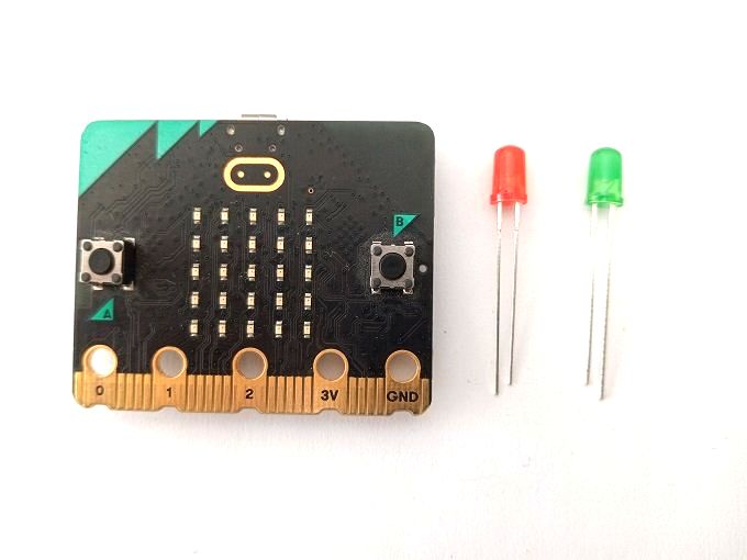
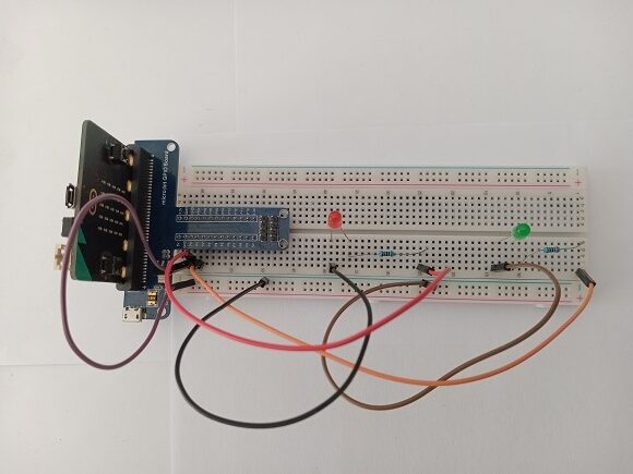
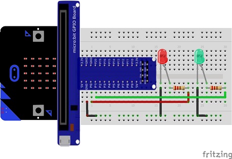
Mounting the Micro:bit board with two LEDs
Once you have these components, you can follow these steps to control the LEDs with a Micro:bit:
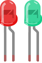
- Connect the red LED:
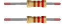
- Connect the longer leg (anode) of the LED to one end of the resistor.
- Connect the other end of the resistor to P0 pin of the Micro:bit's GPIO pins (Pin 0).
- Connect the shorter leg (cathode) of the LED to the Micro:bit's ground (GND) pin.
- Connect the green LED:
- Repeat the same connections as for the red LED, but use a different GPIO pin (Pin 1) on the Micro:bit.
Lighting two LEDs by the Micro:bit card
To light two LEDs using a Micro:bit :
- Open the MakeCode editor (https://makecode.microbit.org/).
- In the editor, start with a "on start" block from the "Basic" category.
- Inside the "on start" block, add the following code:
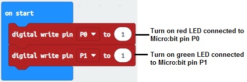
This code will light the two LEDs
- Download the program to the Micro:bit:
- Click on the "Download" button in the MakeCode editor to download the program as a .hex file.
- Transfer the .hex file to the Micro:bit by copying it to the Micro:bit drive that appears when connected via USB.
Now, when you power up the Micro:bit, it will execute the program you created, and you should see the two LEDs light up.
Blink two LEDs by the Micro:bit board
Ensure that each LED has its own resistor and is connected to a separate GPIO pin.
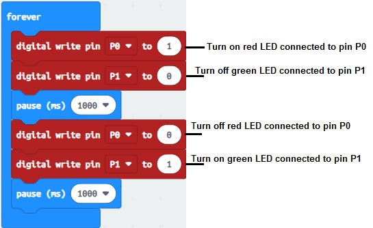
Once you have the connections set up, you can program the Micro:bit to blink the LEDs. Here's an example program using MakeCode:
- Open the MakeCode editor (https://makecode.microbit.org/).
- In the editor, start with a "forever" block from the "Basic" category.
- Inside the "forever" block, add the following code:
- Download the program to the Micro:bit:
- Click on the "Download" button in the MakeCode editor to download the program as a .hex file.
- Transfer the .hex file to the Micro:bit by copying it to the Micro:bit drive that appears when connected via USB.
The program alternates between turning on the red LED and turning off the green LED, then turning off the red LED and turning on the green LED, creating an alternating flashing effect.
Between each LED state change, the program waits for one second using the “pause(ms)(1000)” function to create a one-second pause.
Turn on two LED using the buttons on the Micro:bit board
Once you have the connections set up, you can program the Micro:bit to control the LEDs using the buttons. Here's an example program using MakeCode:
- Open the MakeCode editor (https://makecode.microbit.org/).
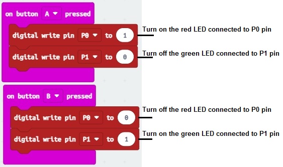
- In the editor, start with an "on button A pressed" block from the "Input" category.
- Place a "digital write pin P0 to 1" block inside the "on button A pressed" block to turn on the red LED connected to Pin 0.
- Place "digital write pin P1 to 0" block inside the "on button A pressed" block to turn off the green LED connected to Pin 1.
- In the editor, insert the "on button B pressed" block from the "Input" category.
- Place "digital write pin P0 to 0" block inside the "on button B pressed" block to turn off the red LED connected to P0.
- Place "digital write pin P1 to 1" block inside the "on button B pressed" block to turn on the green LED connected to P1.
- Download the program to the Micro:bit:
- Click on the "Download" button in the MakeCode editor to download the program as a .hex file.
- Transfer the .hex file to the Micro:bit by copying it to the Micro:bit drive that appears when connected via USB
Now, when you press any of the buttons on the Micro:bit, it will execute the program you created, and both LEDs will turn on simultaneously. Release the buttons to turn the LEDs off again.