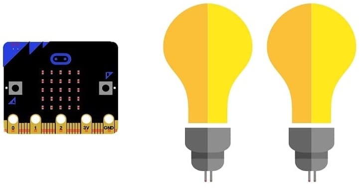
Control two lamps by the Micro:bit card
Tutorial plan
1- The components needed to control two lamps by Micro:bit
2- Mounting the Micro:bit board with two lamps
3- Blink two lamps by the Micro:bit board
4- Turn on two lapms using the buttons on the Micro:bit board
The components needed to control two lamps by Micro:bit board
To control a lamp using a Micro:bit board, you'll need a few components to set up a safe and functional circuit. Here's a list of the necessary components:
Micro:bit Board:

The Micro:bit board, often referred to simply as the Micro:bit, is a small, programmable microcontroller designed for educational purposes and hands-on learning.
The GPIO expansion card for the Micro:bit card

The GPIO expansion board for the Micro:bit board expands the capabilities of the Micro:bit board by adding more input/output (GPIO) pins and additional functionality.
Relay Module:
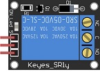
You'll need a relay module that is compatible with the Micro:bit and can switch the high-voltage lamp. Ensure it's rated for the voltage and current required for your lamp.
2 lamps (220V):

The lamp you want to control, which is rated for 220V. Ensure it's in working condition and safe to use.
Power Supply for the Lamp:

You'll need a power source for the lamp, typically a 220V AC power supply.
Wiring:
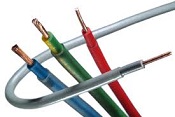
Various wires and cables for connecting the components in your circuit.
Breadboard or Prototyping Board (optional):

A breadboard can be useful for creating temporary connections and organizing your circuit.
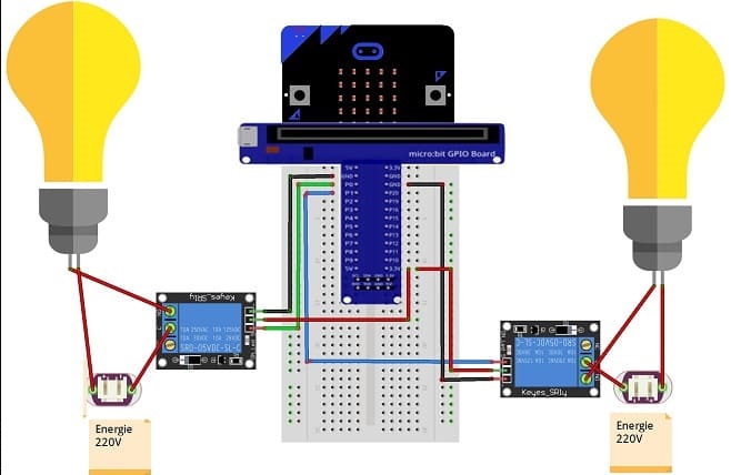
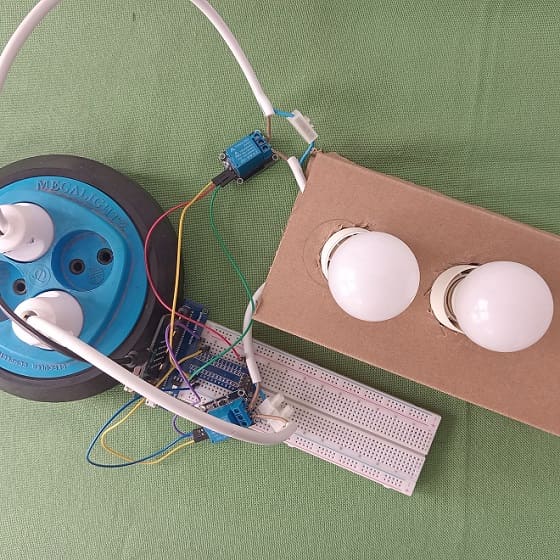
Mounting the Micro:bit board with two lamps
To control two lamps using a Micro:bit board, you will need to use a relay module to safely interface the low-voltage Micro:bit with the high-voltage lamp. Here are the step-by-step instructions to set up the Micro:bit with two lamps:
1- Safety First: Ensure the lamp is disconnected from any power source before proceeding.
2- Connect the first Relay to the Micro:bit:
- Connect the relay's control pin (S) to pin P0 of Micro:bit board
- Connect the pin (+) of relay to pin 3.3V of Micro:bit board.
- Connect the relay's ground pin (GND) to the Micro:bit's GND.
3- Connect the first Lamp and the power supply to the Relay:
- Connect one of the lamp's wires to the normally open (NO) terminal of the relay.
- Connect the phase wire of the power supply to the relay's common (COM) terminal.
- Connect the neutral wire of the power supply directly to the neutral wire of the lamp.
4- Connect the second Relay to the Micro:bit:
- Connect the relay's control pin (S) to pin P1 of Micro:bit board
- Connect the pin (+) of relay to pin 3.3V of Micro:bit board.
- Connect the relay's ground pin (GND) to the Micro:bit's GND.
5- Connect the second Lamp and the power supply to the Relay:
- Connect one of the lamp's wires to the normally open (NO) terminal of the relay.
- Connect the phase wire of the power supply to the relay's common (COM) terminal.
- Connect the neutral wire of the power supply directly to the neutral wire of the lamp.
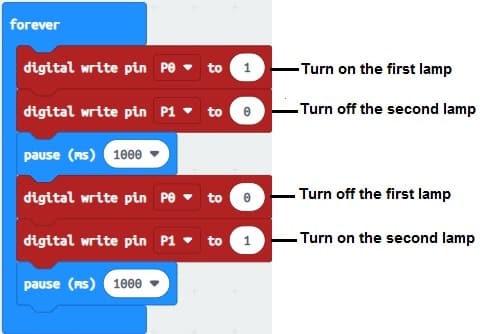
Blink two lamps by the Micro:bit board
Ensure that each lamp has its own resistor and is connected to a separate GPIO pin.
Once you have the connections set up, you can program the Micro:bit to blink the lams. Here's an example program using MakeCode:
1- Open the MakeCode editor (https://makecode.microbit.org/).
2- In the editor, start with a "forever" block from the "Basic" category.
3- Inside the "forever" block, add the following code:
4- Download the program to the Micro:bit:
Click on the "Download" button in the MakeCode editor to download the program as a .hex file.
Transfer the .hex file to the Micro:bit by copying it to the Micro:bit drive that appears when connected via USB.
The program alternates between turning on the first lamp and turning off the second lamp, then turning off the first lamp and turning on the second lamp, creating an alternating flashing effect.
Between each lamp state change, the program waits for one second using the “pause(ms)(1000)” function to create a one-second pause.
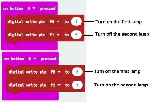
Turn on two lamps using the buttons on the Micro:bit board
Once you have the connections set up, you can program the Micro:bit to control the lamps using the buttons. Here's an example program using MakeCode:
1- Open the MakeCode editor (https://makecode.microbit.org/).
2- In the editor, start with an "on button A pressed" block from the "Input" category.
3- Place a "digital write pin P0 to 1" block inside the "on button A pressed" block to turn on the lamp connected to first relay.
4- Place "digital write pin P1 to 0" block inside the "on button A pressed" block to turn off the lamp connected to second relay.
5- In the editor, insert the "on button B pressed" block from the "Input" category.
6- Place "digital write pin P0 to 0" block inside the "on button B pressed" block to turn off the lamp connected to first relay.
7- Place "digital write pin P1 to 1" block inside the "on button B pressed" block to turn on tthe lamp connected to second relay.
8- Download the program to the Micro:bit:
Click on the "Download" button in the MakeCode editor to download the program as a .hex file.
Transfer the .hex file to the Micro:bit by copying it to the Micro:bit drive that appears when connected via USB
Now, when you press any of the buttons on the Micro:bit, it will execute the program you created, and both lamps will turn on simultaneously. Release the buttons to turn the lamps off again.
0 comment
Leave a comment
Passion for robotics

Recent tutorials


Robotics workshop

Polpular tutorials


Making robots

Most commented tutorials


Robotic arm

Categories
Smart Home