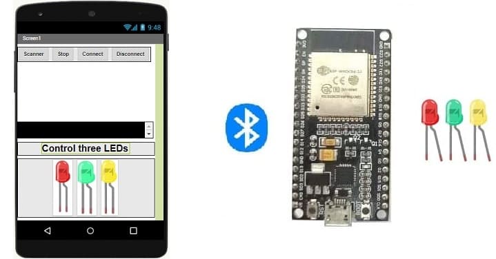
Control three LEDs connected to the ESP32 board via Bluetooth
Tutorial plan
1- The ESP32 board and Bluetooth
2- Why do we use App Inventor to create a mobile application capable of communicating the smartphone with the ESP32 board?
3- Lighting three LEDs connected to the ESP32 board by a smartphone via Bluetooth using the Micropython and MIT Inventor app
4- The components needed to use three LEDs with the ESP32
5- Mounting the ESP32 with three LEDs
The ESP32 board and Bluetooth
The ESP32 is a versatile and widely used microcontroller and system-on-chip (SoC) that offers both Wi-Fi and Bluetooth connectivity. It's popular in various IoT (Internet of Things) and embedded systems projects due to its capabilities and low cost. The Bluetooth functionality on the ESP32 allows it to communicate wirelessly with other devices and peripherals using Bluetooth technology. Here's an overview of the ESP32's Bluetooth capabilities and its common use cases:
1. Bluetooth Classic and Bluetooth Low Energy (BLE): The ESP32 supports both Bluetooth Classic and Bluetooth Low Energy (BLE). Bluetooth Classic is used for more traditional applications like audio streaming and device-to-device communication. BLE, on the other hand, is designed for low-power, short-range communication, making it suitable for various IoT applications.
2. Dual Mode: The ESP32 can operate in dual mode, meaning it can simultaneously support both Bluetooth Classic and BLE connections.
3. Bluetooth Profiles: The ESP32 supports a range of Bluetooth profiles, which define the interactions and behaviors between devices. These profiles include the Serial Port Profile (SPP) for Bluetooth Classic communication and the Generic Attribute Profile (GATT) for BLE communication.
4. Development: To work with Bluetooth on the ESP32, you would typically use the Arduino IDE with the ESP32 Arduino Core or the Espressif IDF (IoT Development Framework). These platforms provide libraries and APIs to interact with Bluetooth features.
5. Use Cases:
- Home Automation: You can use the ESP32 to create smart home devices that communicate with your smartphone or a central hub over Bluetooth or BLE. For example, you could build a smart door lock or a home environmental sensor.
- Wearable Devices: The low-power capabilities of BLE make the ESP32 suitable for wearable devices like fitness trackers or smartwatches.
- Beacon Technology: ESP32 can be used to create BLE beacons for location-based services or proximity detection.
- Wireless Sensor Networks: ESP32 devices can form wireless sensor networks where sensor data is collected and transmitted wirelessly to a central node.
- Remote Control: You can build remote control applications where the ESP32 acts as a controller for various devices, such as robots or drones.
- Data Logging: The ESP32 can gather data from sensors and log it wirelessly to another device, such as a smartphone or a server.
6. Challenges:
- Power Management: Efficient power management is crucial for battery-powered devices. BLE's low-power features help, but managing power usage still requires careful consideration.
- Compatibility: Not all devices support the latest versions of Bluetooth or BLE. Ensuring compatibility with a wide range of devices might require additional testing and adjustments.
- Security: As with any wireless communication, security is a concern. Implementing encryption and secure communication protocols is important, especially for applications that involve sensitive data.
Why do we use App Inventor to create a mobile application capable of communicating the smartphone with the ESP32 board?
MIT App Inventor is a visual programming environment that allows individuals, even those without extensive programming experience, to create mobile applications for Android devices. It's particularly well-suited for creating simple and prototype-level applications that involve interactions with hardware devices like the ESP32. Here's why you might choose to use MIT App Inventor for creating a mobile application that communicates with an ESP32 board:
1- Simplicity and Visual Interface: App Inventor provides a drag-and-drop interface for building the user interface of your app. This makes it accessible to individuals who are not familiar with traditional programming languages. You can visually design the app's layout and user interactions.
2- Rapid Prototyping: If you're looking to quickly create a prototype or proof-of-concept for your idea, App Inventor's visual approach can save you a significant amount of time. You can build functional apps without delving into the complexities of writing code from scratch.
3- Bluetooth Component: App Inventor includes a Bluetooth component that simplifies the process of setting up Bluetooth communication between your app and external devices like the ESP32. You can use this component to establish a connection, send and receive data, and manage Bluetooth interactions.
4- Event-Driven Programming: App Inventor uses a block-based programming paradigm where you assemble blocks to define the behavior of your app. This approach is event-driven, meaning you specify how the app responds to various events, such as button clicks or data received from the ESP32.
5- Beginner-Friendly: MIT App Inventor is designed with beginners in mind. It offers a gentle learning curve and helps individuals grasp programming concepts without getting overwhelmed by complex syntax and structures.
6- Community and Resources: There is a supportive community around MIT App Inventor, offering tutorials, documentation, and forums where you can ask questions and get help with your projects.
7- Integration with ESP32: While the ESP32 typically uses C/C++ for programming, you can set up the ESP32 to communicate with App Inventor-created apps using Bluetooth. This allows you to send and receive data between the ESP32 and your app.
8- Education and Learning: App Inventor is often used in educational settings to introduce programming and app development concepts to students. Creating a mobile app that interacts with hardware like the ESP32 can be an engaging way to learn about technology.
In summary, MIT App Inventor is a valuable tool for quickly creating mobile applications that interact with hardware devices like the ESP32. It's a great choice for beginners, rapid prototyping, and educational purposes.
Lighting three LEDs connected to the ESP32 board by a smartphone via Bluetooth using the Micropython and MIT Inventor app
To light three LED connected to an ESP32 board using a smartphone via Bluetooth, you can follow these steps using MicroPython for the ESP32 and the MIT App Inventor:
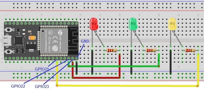
1. Hardware Setup:
- Connect a red LED to a GPIO 23 pin on the ESP32.
- Connect a green LED to a GPIO 22 pin on the ESP32.
- Connect a yellow LED to a GPIO 21 pin on the ESP32.
- Power the ESP32 board.
2. ESP32 MicroPython Code:
Write a simple MicroPython script to control the three LEDs using Bluetooth.
You'll need to use ble_uart_peripheral.py and ble_advertising.py.
you must use the following firmware: esp32-20210902-v1.17.bin .
|
1 2 3 4 5 6 7 8 9 10 11 12 13 14 15 16 17 18 19 20 21 22 23 24 25 26 27 28 29 30 31 32 33 34 35 36 37 38 39 |
########## DIGITAL MANUFACTURING ########## # PIKACHU Project # Authors: Miguel Angel Guzman # Kadriye Nur Bakirci ########################################### ########## IMPORT REQUIRED LIBRARIES ########## import bluetooth from ble_uart_peripheral import BLEUART from machine import Pin red_led=Pin(23, Pin.OUT) # GPIO pin connected to the red LED green_led=Pin(22, Pin.OUT) # GPIO pin connected to the green LED yellow_led=Pin(21, Pin.OUT) # GPIO pin connected to the yellow LED # Create BLE object ble = bluetooth.BLE() # Open UART session for BLE uart = BLEUART(ble) # Define ISR for an UART input on BLE connection def on_rx(): # Read UART string, AppInventor sends raw bytes uart_in = uart.read() # read the message received from the Smartphone via Bluetooth print("UART IN: ", uart_in.decode()) # display the message received from the Smartphone on the Thonny console if (uart_in.decode().find('red_on')==0): red_led.value(1) # Turn on the red LED if (uart_in.decode().find('red_off')==0): red_led.value(0) # Turn off the red LED if (uart_in.decode().find('green_on')==0): green_led.value(1) # Turn on the green LED if (uart_in.decode().find('green_off')==0): green_led.value(0) # Turn off the green LED if (uart_in.decode().find('yellow_on')==0): yellow_led.value(1) # Turn on the yellow LED if (uart_in.decode().find('yellow_off')==0): yellow_led.value(0) # Turn off the yellow LED # Map ISR to UART read interrupt uart.irq(handler=on_rx) uart.close() |
3. MIT App Inventor Setup:
1- Create a new project in MIT App Inventor.
2- Add the BluetoothClient component to your project.
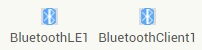
- The "BluetoothLE1" extension indeed refers to a specific extension for MIT App Inventor which allows you to manage Bluetooth Low Energy (BLE) communication in your mobile applications. This extension facilitates the interaction between your App Inventor application and BLE devices, such as sensors, trackers, wearables, etc.
- The "BluetoothClient1" extension in MIT App Inventor allows you to create mobile applications that can connect to Bluetooth devices, such as serial Bluetooth modules (eg HC-06) connected to microcontrollers, Bluetooth audio devices, etc. . This extension facilitates communication with these devices using serial Bluetooth connections.
3- Starting with Android 12, Bluetooth permissions have been enhanced to improve security and user data protection. This is why we must declare the authorizations that your application needs in the AndroidManifest.xml file. For Bluetooth, you'll need to include ACCESS_FINE_LOCATION, BLUETOOTH_SCAN, and possibly BLUETOOTH_CONNECT permissions, depending on the features you're using.
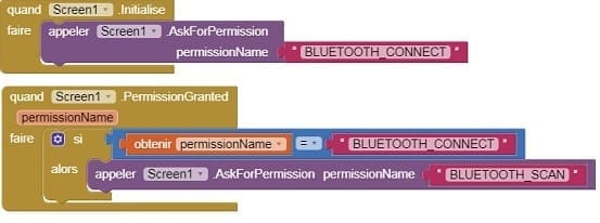
4- Use these programming blocks to connect the smartphone to the ESP32 board via Bluetooth:
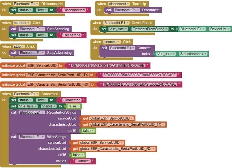
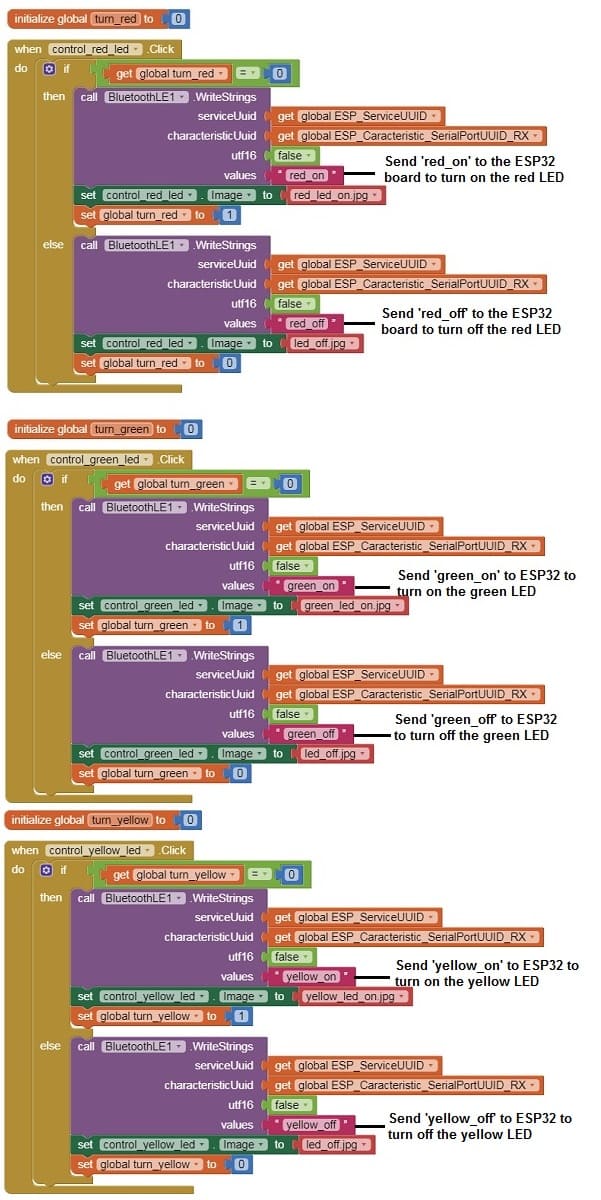
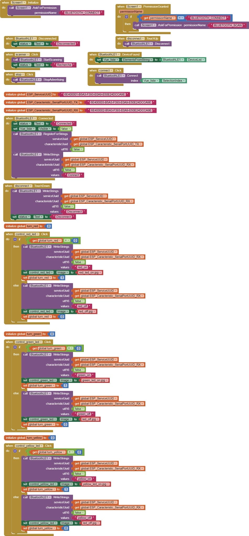
4. MIT App Inventor Blocks:
- Design a simple interface with three buttons to turn the three LEDs on and off.
- Use programming blocks to send Bluetooth commands to the ESP32 when the three buttons are clicked.
Here's a complete example of what this might look like in App Inventor:
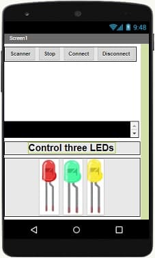
Designer part of the mobile application
Program part of the mobile application
Download aia projectDownload apk file
5. Test:
- Load the MicroPython code onto your ESP32.
- Install the MIT App Inventor app on your smartphone and install the app you created.
- Pair and connect your smartphone with the ESP32 through Bluetooth.
- Open the app and use the button to control the three LEDs connected to the ESP32.
The components needed to control three LEDs by the ESP32 board
To control three LED with the ESP32 board, you will need the following components:
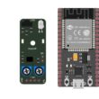
1- ESP32 Board:
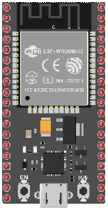
The ESP32 is a microcontroller board that features built-in WiFi and Bluetooth capabilities. It can be programmed and used to control the LED.
2- Three Resistors
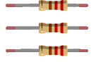
A resistor is an essential electronic component used to impede or limit the flow of electric current in a circuit. It's designed to have a specific resistance value, which is measured in ohms (Ω). Resistors come in various shapes, sizes, and types to suit different applications.
3- Three LEDs (Light Emitting Diode):
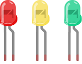
A Light Emitting Diode (LED) is a semiconductor device that emits light when an electric current passes through it. LEDs are widely used in various applications due to their efficiency, small size, and low power consumption.
4- Breadboard:

A breadboard is a useful tool for creating temporary electronic circuits. It allows you to connect components without soldering.
5- Jumper wires:

You will need jumper wires to make electrical connections between the components on the breadboard.
Mounting ESP32 with three LEDs
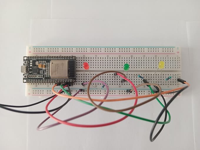
Here are the steps to mount the ESP32 with three LEDs:
1- Place the ESP32 board on the breadboard.
2- Insert the LEDs into the breadboard, connecting them to the output pins of the ESP32 board. For example, connect the red LED to GPIO 23, the green LED to GPIO 22, and the yellow LED to GPIO 21. Make sure to insert the LEDs correctly, paying attention to the polarity (anode and cathode).
3- Connect a resistor in series with each LED. The resistor should be connected between the corresponding GPIO pin and the positive terminal (anode) of the LED.
4- Connect the negative terminal (cathode) of each LED to the ground (GND) of the ESP32 board.
5- Double-check that all connections are properly made and that nothing is short-circuited.
Once the mounting is complete, you can program the ESP32 board to control the LEDs. For example, you can use the MicroPython programming language and the uGPIO module to turn the LEDs on and off.
0 comment
Leave a comment
Passion for robotics

Recent tutorials


Robotics workshop

Polpular tutorials


Making robots

Most commented tutorials


Robotic arm

Categories
Smart Home