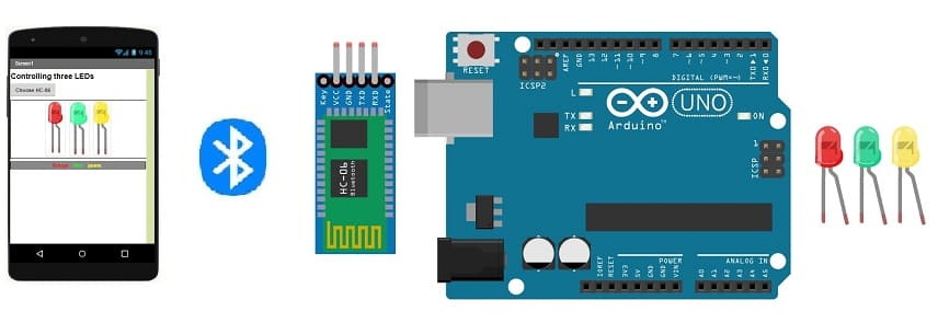
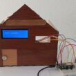
Control three LEDs connected to Arduino UNO via Bluetooth
Tutorial plan
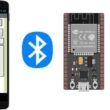
1- The Arduino UNO board and Bluetooth
2- Why do we use App Inventor to create a mobile application capable of communicating the smartphone with the Arduino UNO board?
3- Lighting three LEDs connected to the Arduino UNO board by a smartphone via Bluetooth
4- The components needed to use the HC-06 Bluetooth module and three LEDs with the Arduino UNO
5- Mounting the Arduino UNO with the HC-06 Bluetooth module and three LEDs
6- Arduino UNO programming of the Arduino UNO to receive data from the HC-06 Bluetooth module and light up three LEDs
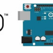
The Arduino UNO board and Bluetooth
The Arduino UNO board and Bluetooth can be used together to create various projects that involve wireless communication. The Arduino UNO is a popular microcontroller board that is widely used for prototyping and creating interactive electronic projects. Bluetooth, on the other hand, is a wireless technology that enables communication between devices over short distances.
To use Bluetooth with an Arduino UNO board, you would typically need to add a Bluetooth module to the board. There are several Bluetooth modules available that can be easily interfaced with the Arduino UNO, such as the HC-05 and HC-06 modules. These modules use the Serial Communication protocol (UART) to communicate with the Arduino.
Here are the general steps to get started with using Bluetooth on an Arduino UNO:
1- Choose a Bluetooth Module: Select a suitable Bluetooth module, such as HC-05 or HC-06, based on your project requirements. These modules are readily available and are relatively easy to work with.
2- Wiring: Connect the Bluetooth module to the Arduino UNO. Typically, you would need to connect the TX pin of the Bluetooth module to the RX pin of the Arduino UNO, and the RX pin of the Bluetooth module to the TX pin of the Arduino UNO. Remember to connect the grounds of both the Bluetooth module and the Arduino together.
3- Power Supply: Make sure the Bluetooth module is properly powered. It usually operates at 3.3V or 5V, so ensure that the voltage levels are compatible with your Arduino UNO and the module.
4- Code: Write an Arduino sketch (program) that communicates with the Bluetooth module using the Serial library. You can send and receive data wirelessly between your Arduino and a Bluetooth-enabled device, such as a smartphone or a computer. Your code should include instructions to establish a Bluetooth connection, send and receive data, and handle any required processing.
5- Pairing and Communication: Once you upload the code to your Arduino UNO and power it up, you can pair your Bluetooth-enabled device with the Bluetooth module on the Arduino. Depending on the module, you might need to enter a specific pairing code.
6- Testing: Test your setup by sending data from your Bluetooth-enabled device to the Arduino UNO and vice versa. For example, you could control an LED, a motor, or any other component connected to your Arduino board.
Remember that specific details may vary depending on the Bluetooth module you are using, so it's important to refer to the datasheet and documentation of your chosen module for accurate wiring, setup, and programming instructions.
With the Arduino UNO and Bluetooth, you can create a wide range of projects, such as remote-controlled robots, home automation systems, wireless sensors, and more. The key is to understand the basics of serial communication and how to interface the Bluetooth module with the Arduino.
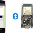
Why do we use App Inventor to create a mobile application capable of communicating the smartphone with the Arduino UNO board?
MIT App Inventor is a visual programming environment that allows individuals with little or no programming experience to create mobile applications for Android devices. It is particularly well-suited for creating mobile applications that communicate with external hardware, such as the Arduino UNO board. Here are some reasons why MIT App Inventor is often used to create mobile applications for communication with Arduino boards:
1- Simplicity and Visual Interface: MIT App Inventor uses a visual drag-and-drop interface that makes it easy for beginners to create mobile applications without having to write complex code. The blocks-based programming approach allows users to build logic by connecting blocks that represent different functions.
2- Rapid Prototyping: App Inventor allows you to quickly prototype and test your ideas. You can create functional applications relatively quickly, which is beneficial when you want to iterate and refine your project.
3- Bluetooth Integration: App Inventor provides built-in components and functions for Bluetooth communication, which simplifies the process of connecting your Android device to an Arduino UNO via Bluetooth. This includes Bluetooth Classic (used by modules like HC-05 and HC-06) and Bluetooth Low Energy (BLE) support.
4- Beginner-Friendly: App Inventor is designed with beginners in mind. Its user-friendly interface and intuitive blocks-based programming make it accessible to individuals who are new to programming or electronics.
5- Real-Time Testing: You can connect your Android device to your computer and test your app in real time using the MIT AI2 Companion app. This immediate feedback helps you troubleshoot and make adjustments on the fly.
6- Arduino-Compatible Libraries: App Inventor offers extensions and libraries specifically designed for Arduino communication. These extensions provide pre-built blocks that simplify the process of sending and receiving data between the Android app and the Arduino.
7- Community and Resources: MIT App Inventor has an active community and a wealth of online resources, tutorials, and sample projects. This means you can find help and guidance as you work on your project.
8- Sensor Integration: You can easily integrate various sensors and features of your Android device, such as the accelerometer, GPS, camera, and more, into your mobile application.
9- Cross-Disciplinary Learning: App Inventor bridges the gap between programming and hardware, making it an excellent tool for learners interested in both software and electronics.
While MIT App Inventor is a powerful tool for creating mobile applications that communicate with Arduino boards, it's important to note that it might have some limitations when it comes to complex applications or advanced features. For more advanced projects, you might eventually need to transition to traditional programming languages and development environments. However, App Inventor remains a valuable entry point for beginners and those looking to quickly prototype and deploy simple mobile applications for Arduino-based projects.
Lighting three LEDs connected to the Arduino UNO board by a smartphone via Bluetooth
To control three LEDs connected to an Arduino UNO board using a smartphone via Bluetooth, you can use MIT App Inventor to create a mobile application and then interface it with the Arduino code. Here's a step-by-step guide to help you get started:
Materials Needed:
Arduino UNO board
three LEDs (with appropriate resistor)
Bluetooth module (e.g., HC-05 or HC-06)
Jumper wires
Smartphone with Bluetooth capabilities
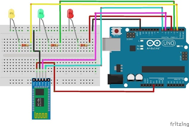
Step 1: Set Up the Arduino Hardware:
1- Connect the anode (longer leg) of the red LED to a digital pin (e.g., pin 4) on the Arduino UNO through a current-limiting resistor (220-330 ohms).
2- Connect the cathode (shorter leg) of the red LED to the ground (GND) pin on the Arduino.
3- Connect the anode (longer leg) of the green LED to a digital pin (e.g., pin 3) on the Arduino UNO through a current-limiting resistor (220-330 ohms).
4- Connect the cathode (shorter leg) of the green LED to the ground (GND) pin on the Arduino.
5- Connect the anode (longer leg) of the yellow LED to a digital pin (e.g., pin 3) on the Arduino UNO through a current-limiting resistor (220-330 ohms).
6- Connect the cathode (shorter leg) of the yellow LED to the ground (GND) pin on the Arduino.
Step 2: Set Up the Bluetooth Module:
1- Connect the TXD pin of the Bluetooth module to pin 6 of the Arduino.
2- Connect the RXD pin of the Bluetooth module to pin 7 of the Arduino.
3- Connect the ground (GND) pin of the Bluetooth module to the GND pin on the Arduino.
4- Connect the VCC pin of the Bluetooth module to the 5V pin on the Arduino.
Step 3: Create the Arduino Code:
|
1 2 3 4 5 6 7 8 9 10 11 12 13 14 15 16 17 18 19 20 21 22 23 24 25 26 27 28 29 30 31 32 33 34 35 36 37 38 39 40 41 42 43 44 45 46 47 48 49 50 51 52 53 54 55 56 |
#include <SoftwareSerial.h> SoftwareSerial hc06(6,7); String cmd=""; int red_led=4; int green_led=3; int yellow_led=2; void setup(){ pinMode(red_led, OUTPUT); pinMode(green_led, OUTPUT); pinMode(yellow_led, OUTPUT); //Initialize Serial Monitor //Serial.begin(9600); //Initialize Bluetooth Serial Port hc06.begin(9600); } void loop(){ //Read data from HC06 while(hc06.available()>0){ cmd+=(char)hc06.read(); } //Select function with cmd if(cmd!=""){ //Serial.print("Command recieved : "); //Serial.println(cmd); // We expect ON or OFF from bluetooth if(cmd=="red_on"){ digitalWrite(red_led, HIGH);// Red LED lights up } if(cmd=="red_off"){ digitalWrite(red_led, LOW);// Red LED lights off } if(cmd=="green_on"){ digitalWrite(green_led, HIGH);// Green LED lights up } if(cmd=="green_off"){ digitalWrite(green_led, LOW);// Green LED lights off } if(cmd=="yellow_on"){ digitalWrite(yellow_led, HIGH);// Yellow LED lights up } if(cmd=="yellow_off"){ digitalWrite(yellow_led, LOW);// Yellow LED lights off } cmd=""; //reset cmd } delay(100); } |
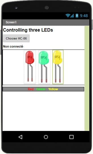
Step 4: Create the MIT App Inventor Mobile App:
1- Open MIT App Inventor (ai2.appinventor.mit.edu) and create a new project.
2- Drag and drop the following components onto the screen:
1 ListPicker (choose_hc06)
1 Button (control_red_led)
1 Button (control_green_led)
1 Button (control_yellow_led)
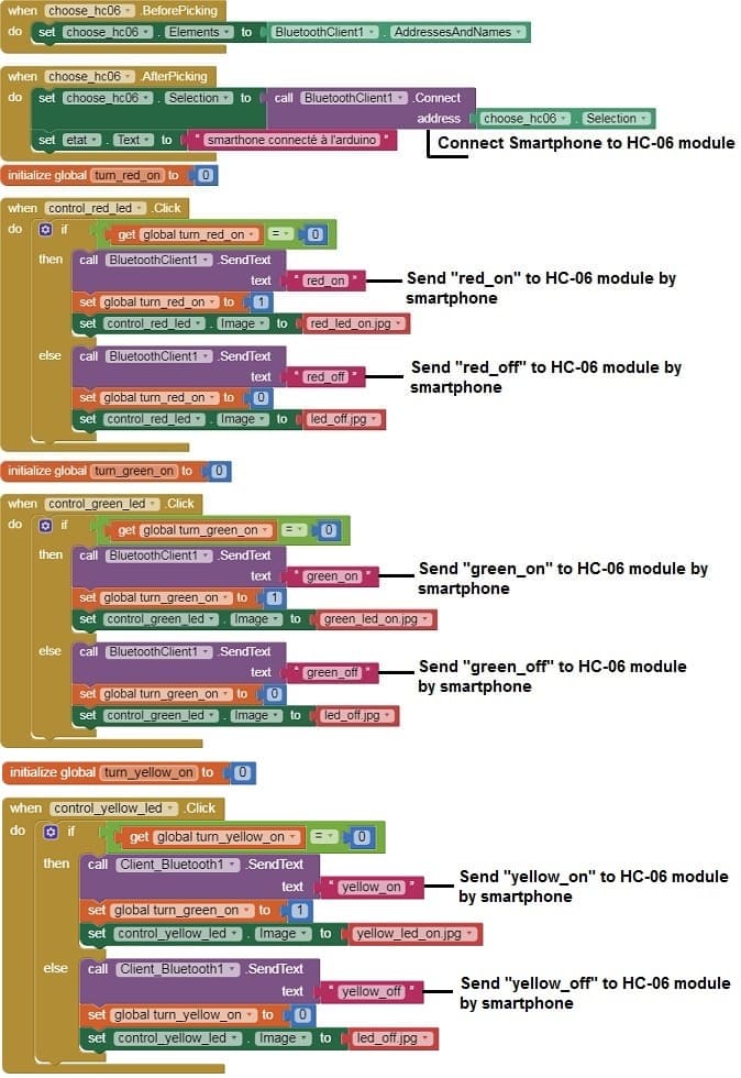
3- Add the BluetoothClient component to your project.
- The "BluetoothLE1" extension indeed refers to a specific extension for MIT App Inventor which allows you to manage Bluetooth Low Energy (BLE) communication in your mobile applications. This extension facilitates the interaction between your App Inventor application and BLE devices, such as sensors, trackers, wearables, etc.
- The "BluetoothClient1" extension in MIT App Inventor allows you to create mobile applications that can connect to Bluetooth devices, such as serial Bluetooth modules (eg HC-06) connected to microcontrollers, Bluetooth audio devices, etc. . This extension facilitates communication with these devices using serial Bluetooth connections.
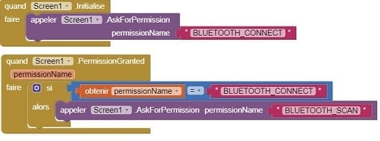
4- Create the following blocks:
a- Starting with Android 12, Bluetooth permissions have been enhanced to improve security and user data protection. This is why we must declare the authorizations that your application needs in the AndroidManifest.xml file. For Bluetooth, you'll need to include ACCESS_FINE_LOCATION, BLUETOOTH_SCAN, and possibly BLUETOOTH_CONNECT permissions, depending on the features you're using.
b- When choose_hc06.AfterPicking
- Call BluetoothClient1.Connect: DeviceAddress = (address of your Bluetooth module)
- When control_led.Click (for red LED on) ,Call BluetoothClient1.SendText: Text = "red_on"
- When control_red_led.Click (for red LED off) ,Call BluetoothClient1.SendText: Text = "red_off"
- When control_green_led.Click (for green LED on) ,Call BluetoothClient1.SendText: Text = "green_on"
- When control_green_led.Click (for green LED off) ,Call BluetoothClient1.SendText: Text = "green_off"
- When control_yellow_led.Click (for yellow LED on) ,Call BluetoothClient1.SendText: Text = "yellow_on"
- When control_yellow_led.Click (for green LED off) ,Call BluetoothClient1.SendText: Text = "yellow_off"
The Designer of mobile application with MIT App Inventor
The program of mobile application with MIT App Inventor
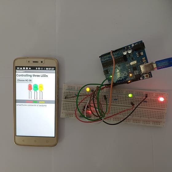
Step 5: Test the System:
1- Upload the Arduino code to the Arduino UNO board.
2- Pair your smartphone with the Bluetooth module on the Arduino.
3- Install and open the MIT App Inventor app on your smartphone.
4- Click the "Connect" button to establish a Bluetooth connection.
5- Click the "Control LED" button to light up the LED, and click again the "Control LED" button to turn it off.
With these steps, you've successfully created a mobile app that can control three LEDs connected to your Arduino UNO board via Bluetooth. This example demonstrates a basic implementation, and you can further customize and expand the functionality based on your project requirements.
The components needed to control three LEDs by the Arduino UNO board and the HC-06 module
To use the HC-06 Bluetooth module and three LEDs with the Arduin UNO, you will need a few components and connections. Here's a list of the required items:
1- Arduino UNO board:
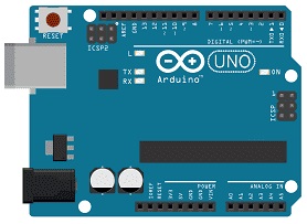
The Arduino UNO board is a popular microcontroller board based on the ATmega328P microcontroller. It is one of the most commonly used Arduino boards and provides a versatile platform for creating interactive electronic projects.
The Arduino UNO board is suitable for beginners and experienced users alike, offering a flexible and accessible platform for prototyping and building various electronic projects, from simple LED blinking to complex robotics and home automation systems.
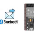
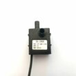
2- HC-06 Bluetooth Module:
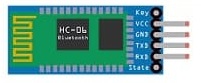
The HC-06 Bluetooth module is a popular and inexpensive Bluetooth module that allows wireless communication between devices over short distances. It is commonly used for projects involving Arduino and other microcontroller platforms. The HC-06 module is a Bluetooth version 2.0 module that supports the Bluetooth Serial Port Profile (SPP), making it relatively easy to interface with microcontrollers like the Arduino.
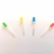
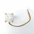
3- Three LEDs (Light Emitting Diode):
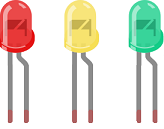
A Light Emitting Diode (LED) is a semiconductor device that emits light when an electric current passes through it. LEDs are widely used in various applications due to their efficiency, small size, and low power consumption.
4- Three resistors
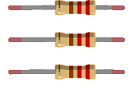
A resistor is a passive electronic component designed to introduce a specific amount of resistance into an electric circuit. Resistance is a measure of how much a material or component opposes the flow of electric current. Resistors are used for various purposes in electronic circuits, such as limiting current, dividing voltage, and providing voltage drops. They come in different shapes, sizes, and materials, and they are color-coded to indicate their resistance value.
4- Breadboard:

A breadboard is a useful tool for creating temporary electronic circuits. It allows you to connect components without soldering.
5- Jumper wires:

These wires are used to make connections.
Mounting the Arduino UNO board with the HC-06 Bluetooth Module and three LEDs
To mount the Arduino UNO board with the KY-032 infrared sensor and an LED, you can follow these steps:
1- Connect the HC-06 Bluetooth Module to the Arduino UNO board:
- Connect the VCC pin of the HC-06 Bluetooth Module to the 5V pin on the Arduino UNO board.
- Connect the GND pin of the HC-06 Bluetooth Module to the GND pin on the Arduino UNO board.
- Connect the TXD pin of the Bluetooth module to pin 6 of the Arduino.
- Connect the RXD pin of the Bluetooth module to pin 7 of the Arduino.
2- Connect red LED to the Arduino UNO board:
- Connect the anode (longer leg) of the LED to a current-limiting resistor, such as a 220-ohm resistor.
- Connect the other end of the resistor to a digital pin on the Arduino UNO board, for example, pin 4.
- Connect the cathode (shorter leg) of the LED to the GND pin on the Arduino UNO board.
3- Connect green LED to the Arduino UNO board:
- Connect the anode (longer leg) of the LED to a current-limiting resistor, such as a 220-ohm resistor.
- Connect the other end of the resistor to a digital pin on the Arduino UNO board, for example, pin 3.
- Connect the cathode (shorter leg) of the LED to the GND pin on the Arduino UNO board.
4- Connect yellow LED to the Arduino UNO board:
- Connect the anode (longer leg) of the LED to a current-limiting resistor, such as a 220-ohm resistor.
- Connect the other end of the resistor to a digital pin on the Arduino UNO board, for example, pin 2.
- Connect the cathode (shorter leg) of the LED to the GND pin on the Arduino UNO board.
0 comment
Leave a comment
Passion for robotics

Recent tutorials
Robotics workshop

Polpular tutorials


Making robots

Most commented tutorials
Robotic arm

Categories
Smart Home