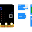
Control four LEDs connected to Micro:bit via Bluetooth
Tutorial plan
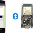
1- The Micro:bit board and Bluetooth
2- Why do we use App Inventor to create a mobile application capable of communicating the smartphone with the Micro:bit board?
3- Lighting four LEDs connected to the Micro:bit board by a smartphone via Bluetooth using Makecode and MIT Inventor app
4- The components needed to use four LEDs with Micro:bit
5- Mounting Micro:bit with four LEDs
The Micro:bit board and Bluetooth
The Micro:bit is a small, programmable microcontroller board designed to teach coding and electronics to children and beginners. It was originally developed by the BBC in the United Kingdom and is now widely used in education worldwide. One of the key features of the Micro:bit is its built-in Bluetooth capability, which allows it to communicate with other devices and be used in various applications.
Here are some important aspects of the Micro:bit's Bluetooth functionality:
Bluetooth Version: The Micro:bit uses Bluetooth Low Energy (BLE) technology, which is a power-efficient version of Bluetooth suitable for battery-operated devices. BLE is commonly used for connecting devices like smartphones, tablets, and other microcontrollers.
Bluetooth Radio: The Micro:bit has a built-in Bluetooth radio module that allows it to both send and receive data wirelessly. This radio module is used for communication between the Micro:bit and other devices.
Bluetooth Pairing: To connect the Micro:bit to another device, such as a smartphone or another Micro:bit, you typically need to pair them. Pairing involves establishing a secure connection between the devices to ensure data privacy and security.
Programming Bluetooth: The Micro:bit can be programmed to use Bluetooth for various purposes. For example, you can create programs that allow the Micro:bit to send sensor data (e.g., temperature, accelerometer data) to a smartphone app or receive commands from a smartphone to control LEDs or other outputs on the Micro:bit.
Block-based and Text-based Programming: Programming the Micro:bit with Bluetooth capabilities can be done using block-based programming languages like MakeCode and text-based languages like MicroPython. MakeCode is a popular choice for beginners due to its visual, drag-and-drop interface, while MicroPython offers more advanced programming capabilities.
Applications: With its Bluetooth capabilities, the Micro:bit can be used in a wide range of applications. For example, it can be used to create remote-controlled cars, interactive games, fitness trackers, weather stations, and more. Its small size and ease of programming make it versatile for various educational and hobbyist projects.
Bluetooth Accessories: There are also accessories and expansion boards available that can extend the Micro:bit's Bluetooth functionality. These accessories can add features such as motor control, additional sensors, and more, enabling even more diverse projects.
In summary, the Micro:bit's built-in Bluetooth functionality makes it a powerful tool for teaching programming and electronics while also allowing for creative and practical projects that involve wireless communication. It's a great platform for beginners and educators to explore the world of coding and electronics.
Why do we use App Inventor to create a mobile application capable of communicating the smartphone with the Micro:bit board ?
MIT App Inventor is a visual programming environment that allows people with little to no programming experience to create mobile applications for Android devices. It's particularly well-suited for educational purposes and rapid prototyping. Here's why App Inventor is often used to create applications for communicating with the Micro:bit board:
Visual Interface: App Inventor provides a visual interface for designing the user interface and behavior of mobile applications. This means you can create applications by dragging and dropping components (like buttons, labels, etc.) and visually connecting them to define their behavior. This makes it accessible to beginners who might find traditional text-based programming intimidating.
Simplicity and Accessibility: App Inventor uses a blocks-based programming model, which means you create applications by snapping together blocks that represent actions, events, and functions. This is more intuitive for beginners and can be a less daunting way to start programming.
Integration with Hardware Components: App Inventor has built-in support for Bluetooth communication. This makes it relatively straightforward to create apps that can communicate with external devices like the Micro:bit. It provides a Bluetooth component that simplifies the process of establishing connections and sending/receiving data.
Immediate Testing: You can connect your Android device to App Inventor via USB or over Wi-Fi, allowing you to instantly test your applications on your phone. This immediate feedback loop is crucial for learning and debugging.
Educational Focus: MIT App Inventor was designed with educational purposes in mind. It's used in schools and educational programs around the world to teach programming concepts and mobile app development. Its simplicity and visual approach make it an excellent choice for introducing students to the world of programming and electronics.
Community and Resources: There's a vibrant community around MIT App Inventor, which means there are plenty of tutorials, forums, and resources available to help beginners get started and troubleshoot any issues they encounter.
Cross-Platform Support: While App Inventor itself is a web-based tool, the apps you create can be installed on Android devices. This makes it accessible to a wide range of users who have Android smartphones or tablets.
In the context of Micro:bit communication, using App Inventor allows educators and beginners to create applications that can control or interact with the Micro:bit without the need for extensive programming knowledge. It provides a user-friendly platform for learning and experimenting with both mobile app development and hardware interaction.
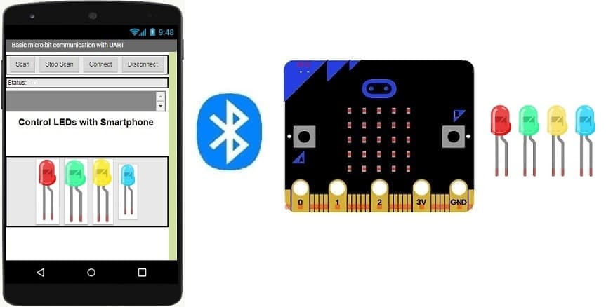
Lighting four LEDs connected to the Micro:bit board by a smartphone via Bluetooth using Makecode and MIT Inventor app
To control four LEDs connected to the Micro:bit board using a smartphone via Bluetooth, you can use MakeCode to program the Micro:bit and create a simple mobile app using MIT App Inventor. Here are the steps to do this:
Programming the Micro:bit using MakeCode:
1- Go to the MakeCode website for the Micro:bit (https://makecode.microbit.org/).
2- Create a new project.
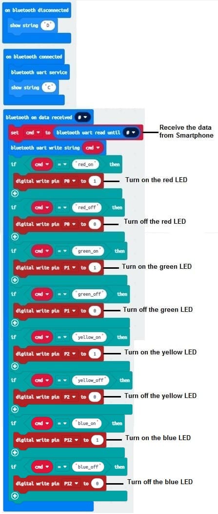
3- In the "Blocks" view, under "Bluetooth," add the "on Bluetooth connected" block to handle Bluetooth connections.
4- Set the pin "0" to "1" to turn on the red LED if the Micro:bit card receives the word 'red_on'
5- Duplicate the "digital write pin" block and set the pin "0" to "0" to turn off the red LED when the Micro:bit card receives the word 'red_off'.
6- Set the pin "0" to "1" to turn on the green LED if the Micro:bit card receives the word 'green_on'
7- Duplicate the "digital write pin" block and set the pin "0" to "0" to turn off the green LED when the Micro:bit card receives the word 'green_off'.
8- Set the pin "0" to "1" to turn on the yellow LED if the Micro:bit card receives the word 'yellow_on'
9- Duplicate the "digital write pin" block and set the pin "0" to "0" to turn off the yellow LED when the Micro:bit card receives the word 'yellow_off'.
10- Set the pin "0" to "1" to turn on the blue LED if the Micro:bit card receives the word 'blue_on'
11- Duplicate the "digital write pin" block and set the pin "0" to "0" to turn off the blue LED when the Micro:bit card receives the word 'blue_off'.
12- Your code might look something like this:
Creating the MIT App Inventor Mobile App:
1- Go to the MIT App Inventor website (http://ai2.appinventor.mit.edu/).
2- Create a new project.
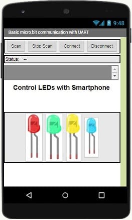
3- Design the user interface of your app. You might have a simple button to turn on and turn off the LED
4- Add the components to your app. ![]()
- The "BluetoothLE1" extension indeed refers to a specific extension for MIT App Inventor which allows you to manage Bluetooth Low Energy (BLE) communication in your mobile applications. This extension facilitates the interaction between your App Inventor application and BLE devices, such as sensors, trackers, wearables, etc.
- The "BluetoothClient1" extension in MIT App Inventor allows you to create mobile applications that can connect to Bluetooth devices, such as serial Bluetooth modules (eg HC-06) connected to microcontrollers, Bluetooth audio devices, etc. . This extension facilitates communication with these devices using serial Bluetooth connections.
- The "Microbit_UART1" extension allows you to use UART (Universal Asynchronous Receiver-Transmitter) communication with the Micro:bit card in the MakeCode programming environment.
- The "Notifier1" extension in MIT App Inventor is a component for displaying notifications or messages to the user of an application. It can be used to send pop-up messages, alerts or important information to the user while the application is running. It is a useful component to improve user experience by providing contextual information.
5- Starting with Android 12, Bluetooth permissions have been enhanced to improve security and user data protection. This is why we must declare the authorizations that your application needs in the AndroidManifest.xml file. For Bluetooth, you'll need to include ACCESS_FINE_LOCATION, BLUETOOTH_SCAN, and possibly BLUETOOTH_CONNECT permissions, depending on the features you're using.
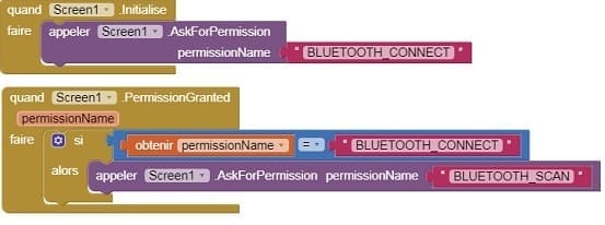
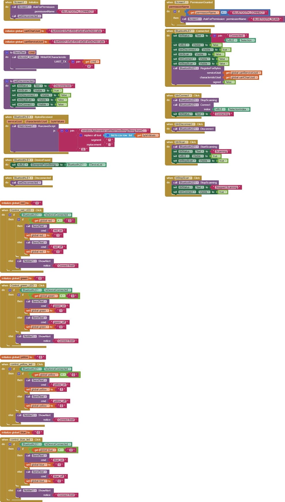
6- Use these programming blocks to connect the smartphone to the Micro:bit board via Bluetooth:
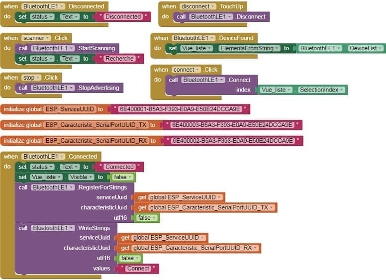
4. MIT App Inventor Blocks:
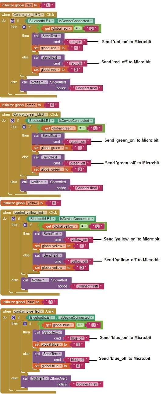
- Design a simple interface with four buttons to turn the four LEDs on and off.
- Use programming blocks to send Bluetooth commands to the Micro:bit when the button is clicked.
Here's a complete example of what this might look like in App Inventor:
Designer part of the mobile application
Program part of the mobile application
 Download projectDownload apk file
5. Test:
- Load the Makecode code onto your Micro:bit.
- Install the MIT App Inventor app on your smartphone and install the app you created.
- Pair and connect your smartphone with the Micro:bit through Bluetooth.
- Open the app and use the buttons to control the four LEDs connected to the Micro:bit.
With these steps completed, you should be able to control the LEDs on your Micro:bit from your smartphone via Bluetooth.
Pressing the " red LED" button in the app should turn on the red LED, and pressing again the "red LED" button should turn off the red LED.
Pressing the " green LED" button in the app should turn on the green LED, and pressing again the "green LED" button should turn off the green LED.
Pressing the " yellow LED" button in the app should turn on the yellow LED, and pressing again the "yellow LED" button should turn off the yellow LED.
Pressing the " blue LED" button in the app should turn on the blue LED, and pressing again the "blue LED" button should turn off the blue LED.
The components needed to control three LED by Micro:bit
To control an LED using a Micro:bit, you will need the following components:
Two Micro:bit board

The Micro:bit board is a small, programmable development board designed for educational purposes and beginner-friendly programming. It was created as a collaboration between several organizations, including the BBC, in order to promote computer science education and coding skills among young learners.
With the Micro:bit board, users can create a wide range of projects and interactive applications. They can write programs to control the LEDs, read sensor data, respond to button presses, and communicate with other devices using Bluetooth. The versatility of the board allows for creative exploration and learning in areas such as robotics, Internet of Things (IoT), and wearable technology.
The Micro:bit has gained popularity in schools, coding clubs, and maker communities around the world as an affordable and engaging tool for teaching coding concepts and electronics. Its compact size and user-friendly interface make it an excellent choice for beginners, while its capabilities and extensibility provide room for more advanced projects as well.
The GPIO expansion card for the Micro:bit card

The GPIO expansion board for the Micro:bit board expands the capabilities of the Micro:bit board by adding more input/output (GPIO) pins and additional functionality.
LEDs:
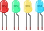
You will need three LEDs of your choice. These can be regular LEDs or RGB LEDs, depending on your project requirements.
Resistors:
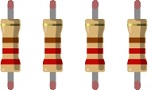
LEDs require current-limiting resistors to prevent them from burning out. The value of the resistor depends on the forward voltage and current rating of the LEDs. A typical value for a standard LED is around 220-470 ohms.
Jumper wires

You will need jumper wires to connect the Micro:bit to the LED and the current-limiting resistor. Make sure you choose the appropriate type of jumper wires (e.g., male-to-male, male-to-female, or female-to-female) based on your specific setup.
Test plate

The breadboard is a common tool used in robotics and electronics to create circuit prototypes and temporary connections. It makes it easy to test and connect electronic components together without having to solder the connections.
Once you have gathered these components, you can properly connect them and program the Micro:bit board to control the LED as needed. Be sure to follow good connection and safety practices when handling electronic components.
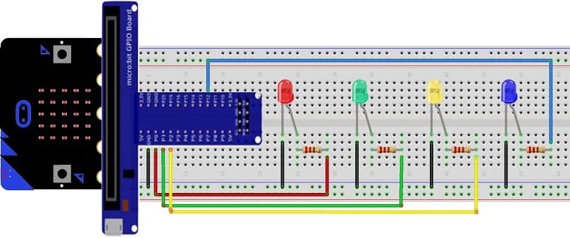
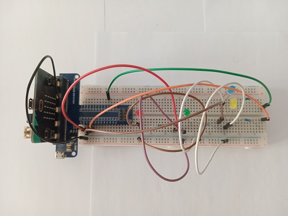
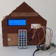
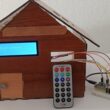
Mounting the Micro:bit board with four LEDs
To mount the Micro:bit board with four LEDs, you will need a breadboard and some additional components. Here's a step-by-step guide:
1- Connect the Micro:bit to the breadboard.
2- Connect the LEDs to the breadboard:
- Insert the four LEDs into the breadboard, making sure that the shorter leg (cathode) of each LED is connected to GND pin of Micro:bit.
- Connect a 220-ohm resistor to the longer leg (anode) of each LED.
- Connect the other end of each resistor to (P0, P1, P2 and P12).
Now, when you write code to control the LEDs using the specified pins, the Micro:bit will send signals to the LEDs through the breadboard, and they will light up accordingly.
0 comment
Leave a comment
Passion for robotics

Recent tutorials
Robotics workshop

Polpular tutorials


Making robots

Most commented tutorials
Robotic arm

Categories
Smart Home