Control four LEDs by Micro:bit
Tutorial plan
1- Role of LEDs in robotics
2- The components needed to control four LEDs by Micro:bit
3- Mounting the Micro:bit board with four LEDs
4- Lighting four LEDs by the Micro:bit card
5- Turn on four LEDs alternately
6- Turn on four LED using the buttons on the Micro:bit board
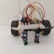
Role of LEDs in robotics
LEDs (Light-Emitting Diodes) play various roles in robotics, offering both functional and aesthetic benefits. Here are some common roles of LEDs in robotics:
Indication and Status Feedback: LEDs are often used to provide visual feedback in robotics systems. They can be programmed to indicate the status of different components or subsystems. For example, an LED might indicate whether the robot is powered on, if a specific sensor is activated, or if a task or action is in progress.
Object Detection and Sensing: In certain robotic applications, LEDs are utilized as light sources for object detection and sensing. For instance, infrared LEDs can be used in conjunction with infrared sensors to enable proximity sensing or line following. By emitting light and measuring the reflected or blocked signals, the robot can detect and navigate its environment.
Communication and Signaling: LEDs can be employed as part of a communication system between robots or between a robot and humans. By using different colors, blinking patterns, or sequences, LEDs can convey specific messages or signals. For example, a robot might use LEDs to signal that it is ready to receive commands, indicate a specific error condition, or display a warning.
Decorative and Aesthetic Purposes: LEDs can also serve as decorative elements in robotics. They can be integrated into a robot's design to enhance its appearance or create visual effects. This is particularly common in educational or hobbyist robotics projects, where LEDs are used to make the robot more visually appealing or to give it a distinctive look.
Safety and Visibility: In certain robotic applications, LEDs are employed to enhance safety and improve visibility. For instance, robots operating in low-light environments or hazardous areas can be equipped with bright LEDs to make them more visible to humans or to indicate their presence.
The components needed to control foor LEDs by Micro:bit
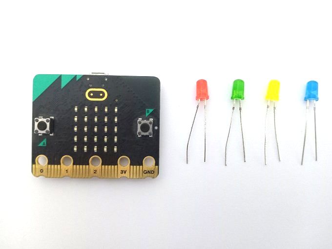
To control three LEDs using a Micro:bit, you will need the following components:
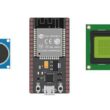
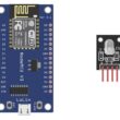
Micro:bit board: The Micro:bit is a small, programmable development board with built-in sensors and GPIO pins.
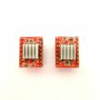
The GPIO expansion card for the Micro:bit card expands the capabilities of the Micro:bit board by adding more input/output (GPIO) pins and additional functionality. 
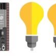
LEDs: You will need three LEDs of your choice. These can be regular LEDs or RGB LEDs, depending on your project requirements.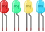
Resistors: LEDs require current-limiting resistors to prevent them from burning out. The value of the resistor depends on the forward voltage and current rating of the LEDs. A typical value for a standard LED is around 220-470 ohms.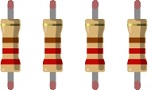
Jumper wires: You will need jumper wires to connect the Micro:bit's GPIO pins to the LEDs and resistors.
If you prefer to use a breadboard for easy prototyping and connection, you can use it to connect the LEDs, resistors, and jumper wires.
With these components, you can connect the LEDs to the Micro:bit's GPIO pins using the resistors to limit the current. You can then program the Micro:bit to control the GPIO pins and turn the LEDs on or off.
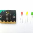
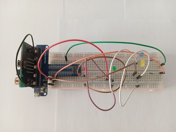
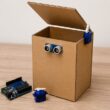
Mounting the Micro:bit board with four LEDs
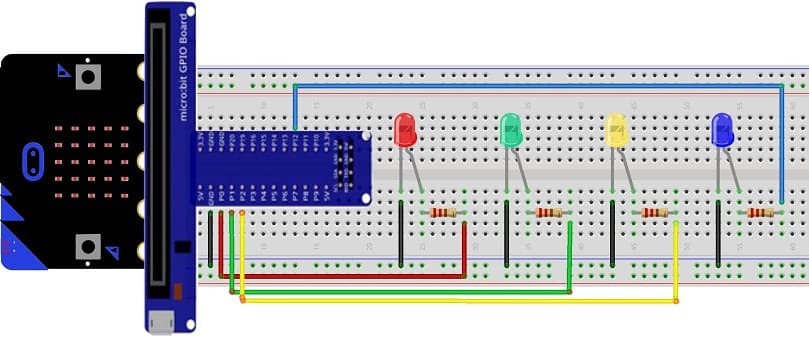
To mount the Micro:bit board with four LEDs, you will need a breadboard and some additional components. Here's a step-by-step guide:
1- Connect the Micro:bit to the breadboard.
2- Connect the LEDs to the breadboard:
Insert the four LEDs into the breadboard, making sure that the shorter leg (cathode) of each LED is connected to GND pin of Micro:bit.
Connect a 220-ohm resistor to the longer leg (anode) of each LED.
Connect the other end of each resistor to (P0, P1, P2 and P12).
Now, when you write code to control the LEDs using the specified pins, the Micro:bit will send signals to the LEDs through the breadboard, and they will light up accordingly.
Lighting four LEDs by the Micro:bit card
To light up four LEDs using the Micro:bit board and MakeCode, you can follow these steps:
1- Open the MakeCode editor on your browser by visiting https://makecode.microbit.org/.
2- Create a new project or open an existing one.
3- Drag and drop a "on start" block from the "Basic" category to the workspace.
4- Inside the "on start" block, add four "digital write pin" blocks from the "Pins" category.
5- Set the pins for each LED. For example, use P0 for the red LED, P1 for the green LED, P2 for the yellow LED, and P12 for the fourth LED.
6- Set the value of each pin to 1 to turn on the corresponding LED.
Here's an example code that lights up the four LEDs:
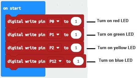
In this code, each LED is turned on.
Turn on four LEDs alternately by the Micro:bit card
To turn on four LEDs alternately using the Micro:bit board and MakeCode, you can follow these steps:
1- Open the MakeCode editor on your browser by visiting https://makecode.microbit.org/.
2- Create a new project or open an existing one.
3- Drag and drop a "forever" block from the "Basic" category to the workspace.
4- Inside the "forever" block, add a "digital write pin" block from the "Pins" category.
5- Select the pin for the red LED (e.g., P0) and set its value to 1 to turn on the LED.
6- Add a "pause" block from the "Basic" category to set the duration for which the LED will stay on. For example, use a pause of 1000 milliseconds (1 seconds).
7- Add another "digital write pin" block after the pause and set the pin value to 0 to turn off the LED.
8- Repeat steps 4 to 7 for the remaining three LEDs, using different pins for each LED.
Here's an example code that turns on the four LEDs alternately:
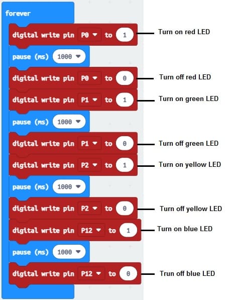
In this code, each LED is turned on and off with a pause of 500 milliseconds (0.5 seconds) between each transition. The LEDs connected to pins P0, P1, P2, and P12 will light up alternately. You can adjust the pin numbers and pause durations according to your specific setup and desired timing.
Turn on four LEDs using the buttons on the Micro:bit board
To turn on four LEDs using the buttons on the Micro:bit board and MakeCode, you can follow these steps:
1- Open the MakeCode editor on your browser by visiting https://makecode.microbit.org/.
2- Create a new project or open an existing one.
3- Drag and drop an "on button A pressed" block and an "on button B pressed" block from the "Input" category to the workspace.
4- Inside the "on button A pressed" block, add four "digital write pin" blocks from the "Pins" category.
5- Set the pins for each LED. For example, use P0 for the red LED, P1 for the green LED, P2 for the yellow LED, and P12 for the blue LED.
6- Set the value of each pin to 1 to turn on the corresponding LED.
7- Inside the "on button B pressed" block, add four "digital write pin" blocks and set the value of each pin to 0 to turn off all the LEDs.
Here's an example code that turns on the four LEDs when button A is pressed and turns them off when button B is pressed:
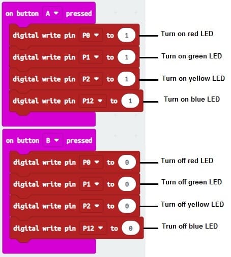
In this code, when you press button A, all four LEDs connected to pins P0, P1, P2, and P12 will turn on. When you press button B, all the LEDs will turn off. You can adjust the pin numbers and customize the code to match your specific configuration and desired behavior.
0 comment
Leave a comment
Passion for robotics

Recent tutorials


Robotics workshop

Polpular tutorials


Making robots

Most commented tutorials


Robotic arm

Categories
Smart Home