Control a servo motor by Micro:bit
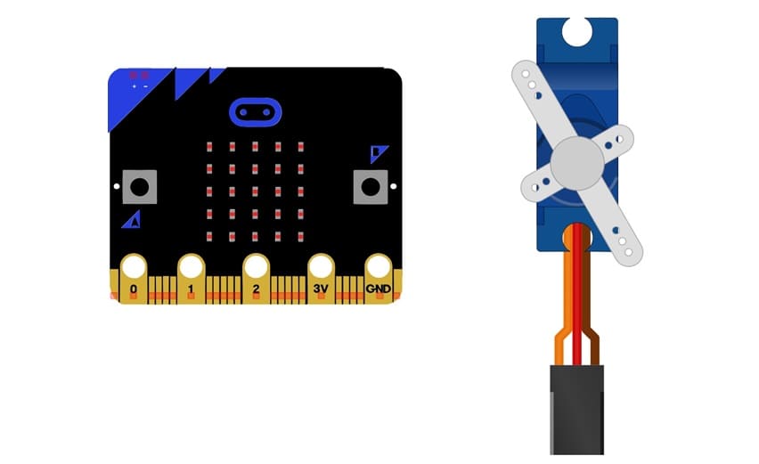
Tutorial plan
1- Presentation of servo motor
2- Necessary components to control a servo motor
3- Wiring Setup
4- Programming Micro:bit with Makecode
Presentation of servo motor
A servo motor is a rotary or linear actuator that provides precise control of angular or linear position, velocity, and acceleration. It is widely used in applications requiring controlled movement, such as robotics, automation, and model making.
A servo motor receives a control signal that specifies the desired position or speed. The control circuit compares this signal to the feedback from the position sensor and adjusts the motor accordingly to reach or maintain the desired position or speed.
Applications of Servo Motors
Robotics: Joint movement in robotic arms or legs.
Aviation: Used in control surfaces like flaps and ailerons.
Cameras: Pan and tilt mechanisms.
Industrial Automation: Precision cutting, assembly lines, and conveyor systems.
Automobiles: Applications like cruise control and automatic braking.
Model Making: Steering systems in remote-controlled cars or controlling flaps in model planes.
Necessary components to control a servo motor
To control a servo motor with Micro:bit, you'll need the following components:
Micro:bit:
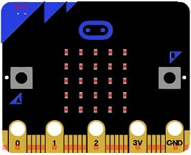
The main microcontroller board to control the servo motor.
The GPIO expansion card for the Micro:bit card
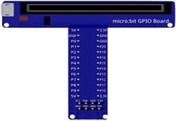
The GPIO expansion board for the Micro:bit board expands the capabilities of the Micro:bit board by adding more input/output (GPIO) pins and additional functionality.
Servomotor:

A servo motor receives a control signal that specifies the desired position or speed.
Jumper Wires :
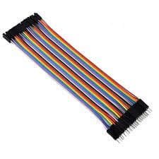
Jumper wires will be used to make connections between the components.
Breadboard (Optional):
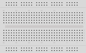
A breadboard is a versatile and reusable platform used for prototyping and testing electronic circuits without the need for soldering.
Wiring Setup
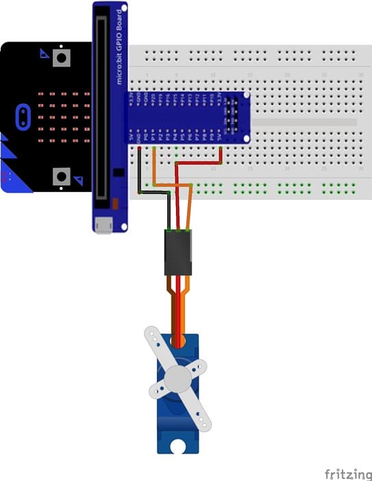
Servo Signal Wire: Connect the signal wire (typically yellow or white) of the servo motor to one of the micro:bit's pins capable of PWM output (e.g., P1).
Servo Power Wire: Connect the servo's power wire (usually red) to the 5V pin on the GPIO.
Servo Ground Wire: Connect the ground wire (usually black or brown) of the servo to the GND pin of the micro:bit. If using an external power source, ensure the ground of the power source is connected to the micro:bit's ground.
Programming Micro:bit with Makecode
You can program the micro:bit using the MakeCode Editor.
1- Go to Microsoft MakeCode and start a new project.
2- In MakeCode, open the Blocks Editor (https://makecode.microbit.org/) .
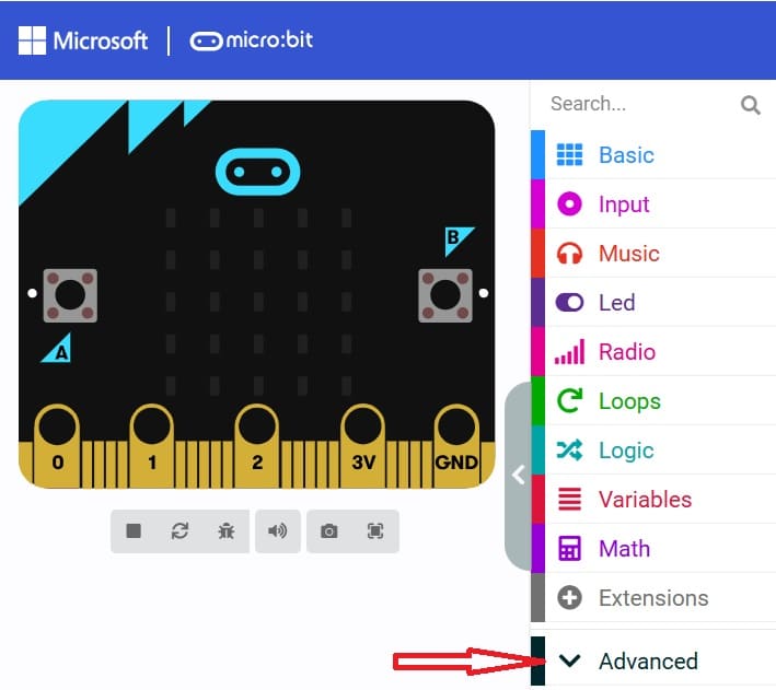
3- Go to advanced :
4- Go to Pin and choose 'servo write pinP0 to 180' instruction :
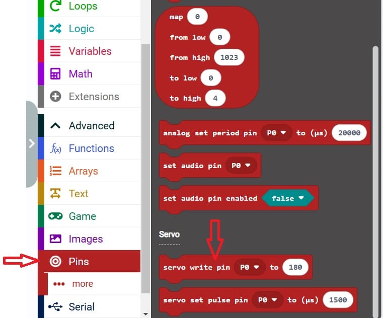
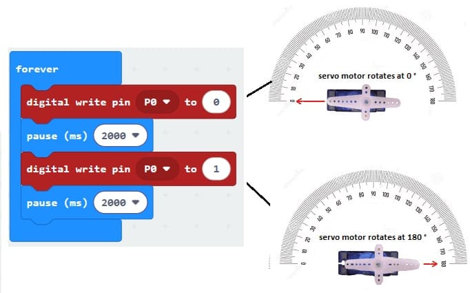
5- Use the blocks to control the servo motor to alternate the servo motor between 0° and 180° with a 2-seconds delay.
