Role of LEDs in robotics
LEDs (Light Emitting Diodes) play various roles in robotics. Here are some common uses of LEDs in robotics:
- Status Indicators: LEDs are often used as visual indicators to convey information about the status of a robot. For example, different colored LEDs can represent different modes of operation such as power on/off, charging, low battery, error conditions, or specific actions being performed by the robot.
- Sensor Feedback: LEDs can be used as part of a sensor system to provide feedback on the readings or measurements being taken. For instance, in line-following robots, an array of LEDs can be used to detect and track a line on the ground, with each LED indicating the position of the line relative to the robot's sensors.
- Communication: LEDs can be utilized to establish visual communication between robots or between a robot and a human. By blinking or changing colors, LEDs can convey simple messages or signal specific actions or requests.
- Ambient Lighting: LEDs can be employed to provide ambient lighting in robotic systems. This is particularly useful when operating in low-light conditions or for creating visual effects.
- Aesthetics: LEDs are often used in robotics for aesthetic purposes. They can enhance the appearance of a robot, making it more visually appealing or giving it a distinct character.
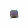
- Display and Feedback: In some cases, robots incorporate LED displays to provide information or feedback. These displays can show alphanumeric characters, symbols, or graphical representations to communicate data or instructions.
The components needed to control an LED by Micro:bit
To control an LED using a Micro:bit, you will need the following components:
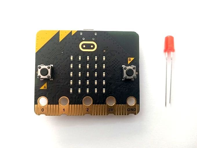
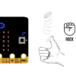
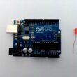
Micro:bit board

The Micro:bit is a small programmable development board with an ARM microcontroller. It has built-in LED indicators and GPIO (General Purpose Input/Output) pins that can be used to control external components like an LED.
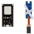
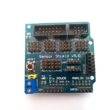
The GPIO expansion card for the Micro:bit card

The GPIO expansion board for the Micro:bit board expands the capabilities of the Micro:bit board by adding more input/output (GPIO) pins and additional functionality.
LED (Light Emitting Diode)
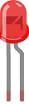
Choose an LED of your preferred color. LEDs have two leads, a longer positive (anode) lead and a shorter negative (cathode) lead.
Resistor
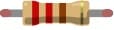
To limit the current flowing through the LED and protect it from excessive current, you will need a current-limiting resistor. The value of the resistor depends on the specific LED and the power supply voltage. A typical value is around 220-330 ohms, but you can calculate the exact value using Ohm's law.
Jumper wires

You will need jumper wires to connect the Micro:bit to the LED and the current-limiting resistor. Make sure you choose the appropriate type of jumper wires (e.g., male-to-male, male-to-female, or female-to-female) based on your specific setup.
Test plate

The breadboard is a common tool used in robotics and electronics to create circuit prototypes and temporary connections. It makes it easy to test and connect electronic components together without having to solder the connections.
Once you have gathered these components, you can properly connect them and program the Micro:bit board to control the LED as needed. Be sure to follow good connection and safety practices when handling electronic components.
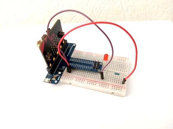
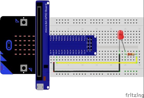
Mounting the Micro:bit board with an LED
To mount an LED with the Micro:bit board, you can follow these steps:
- Connect the LED and resistor: Insert one leg of the resistor into the positive leg of the LED (anode, usually the longer leg), and connect the other leg of the resistor to pin P0 on the Micro:bit board . Next, connect the negative leg of the LED (cathode, usually the shorter leg) to ground (GND) on the Micro:bit board.
- Connect the resistor to the P0 pin: Connect the other end of the resistor to the P0 pin of the Micro:bit board.
Lighting an LED by the Micro:bit card
To light an LED using a Micro:bit, follow these steps:
- Access the MakeCode online editor by visiting https://makecode.microbit.org/.
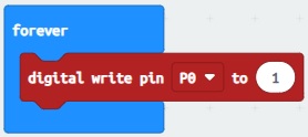
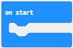
- Drag the "on start" block from the "Basic" section into the workspace.
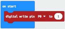
- Insert the block “digital write pin P0 to value 1” from the “Pins” section in the workspace, in the “on start” block.
- Connect your Micro:bit card to your computer using a USB cable.
- Click the "Download" button (down arrow) in the lower left corner of the online Makecode editor.
- Send the .hex file to the Micro:bit card
- When the file copy is complete, the specified LED will light up on the Micro:bit board.
Turn on an LED using the buttons on the Micro:bit board
To turn on an LED using the buttons on the Micro:bit board, you can follow these steps:
- Set up the hardware: Connect an LED to one of the GPIO pins on the Micro:bit board. The most commonly used pin for connecting an LED is pin 0, which is labeled as "0" on the board. Connect the longer leg (anode) of the LED to the GPIO pin (e.g., pin 0) and the shorter leg (cathode) to a GND pin on the Micro:bit board.
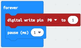
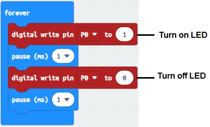
- Write the code: Use the Micro:bit's programming environment, such as the MakeCode editor, to write the code. Here's an example code:
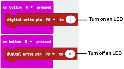
This code listens for button presses on button A and button B. When button A is pressed, it turns on the LED by setting the GPIO pin (pin 0) to a high state (1). Similarly, when button B is pressed, it turns off the LED by setting the GPIO pin to a low state (0).
- Download and flash the code: Connect the Micro:bit board to your computer using a USB cable. Open the MakeCode editor and paste the code into the editor. Click on the "Download" button to download the compiled code onto the Micro:bit. The Micro:bit will appear as a removable storage device. Drag and drop the downloaded file onto the Micro:bit drive to flash the code onto the board.
Once the code is flashed onto the Micro:bit, you can disconnect it from the computer, press the A or B button, and observe the LED turning on and off accordingly.
Dimming of the LED by the Micro:bit board
To dim an LED using a Micro:bit board, you can use Pulse Width Modulation (PWM). The Micro:bit has some pins that support PWM output, such as P0, P1, P2, P3, P4, P6, P7, P8, P9, P10, and P11.
In our case we will vary the intensity of an LED connected to pin P0 of the Micro:bit card.
We will use the graphical programming language MakeCode. Here are the steps to follow:
- Access the MakeCode online editor by visiting https://makecode.microbit.org/.
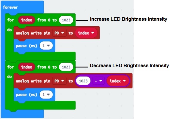
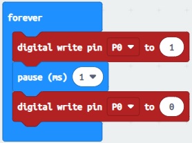
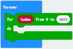
- Drag the "forever" block from the "Basic" section into the workspace.

- Insert the block “for index varying from 0 to 1023” of the “Loops” section in the space of workspace, in the “forever” block.
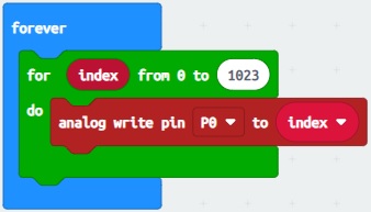
- Insert the instruction "analog write pin P0 to 1023" from the "Pins" section in the workspace, in the block "for index from 0 to 1023" to gradually increase the intensity of the LED.
- Then insert the “pause” instruction to slow down the speed of the LED dimming.
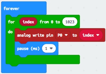
- Repeat the following 3 steps to decrease the light intensity of the LED.
Finally, we get the following program: