Control a lamp by the Micro:bit board
Tutorial plan
1- How to turn on 220V lamp using the Micro:bit card ?
2- The components needed to control a lamp by Micro:bit board
3- Mounting the Micro:bit board with a lamp
4- Lighting a lamp by the Micro:bit board
5- Blink a lamp by the Micro:bit board
6- Turn on a lamp using the buttons on the Micro:bit board
How to turn on 220V lamp using the Micro:bit card ?
Turning on a 220V lamp using a Micro:bit card requires an intermediate component like a relay to safely interface the low-voltage Micro:bit with the high-voltage lamp.
A relay is used between a 220V lamp and a Micro:bit card for several important reasons:
Electrical Isolation: The Micro:bit operates at a much lower voltage (usually 3.3V or 5V) compared to the 220V used by the lamp. Using a relay provides electrical isolation between these two systems, which helps prevent damage to the Micro:bit and reduces the risk of electrical shock.
Voltage Compatibility: The Micro:bit, like most microcontrollers, cannot directly switch high-voltage loads such as a 220V lamp. The relay acts as a switch controlled by the Micro:bit, allowing the control of high-voltage devices with a low-voltage input.
Safety: Using a relay enhances safety by preventing potential short circuits that might occur if the Micro:bit were directly connected to a high-voltage load. The relay is designed to handle such loads safely.
Durability: Electronic components, including the Micro:bit, are typically not designed to handle the high currents and voltages required for controlling high-voltage devices like lamps. Using a relay extends the lifespan of the Micro:bit and avoids premature wear and tear of its components.
Flexibility: Using a relay allows you to control various high-voltage loads by simply changing the connections to the relay, rather than having to adapt the Micro:bit for each specific application.
The components needed to control a lamp by Micro:bit board
To control a lamp using a Micro:bit board, you'll need a few components to set up a safe and functional circuit. Here's a list of the necessary components:
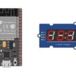
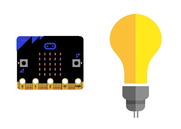
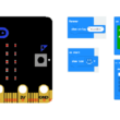
Micro:bit Board:

The Micro:bit board, often referred to simply as the Micro:bit, is a small, programmable microcontroller designed for educational purposes and hands-on learning.
The GPIO expansion card for the Micro:bit card

The GPIO expansion board for the Micro:bit board expands the capabilities of the Micro:bit board by adding more input/output (GPIO) pins and additional functionality.
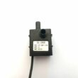
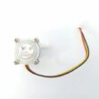
Relay Module:
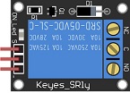
You'll need a relay module that is compatible with the Micro:bit and can switch the high-voltage lamp. Ensure it's rated for the voltage and current required for your lamp.
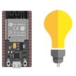
Lamp (220V):

The lamp you want to control, which is rated for 220V. Ensure it's in working condition and safe to use.
Power Supply for the Lamp:

You'll need a power source for the lamp, typically a 220V AC power supply.
Wiring:
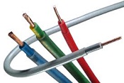
Various wires and cables for connecting the components in your circuit.
Breadboard or Prototyping Board (optional):

A breadboard can be useful for creating temporary connections and organizing your circuit.
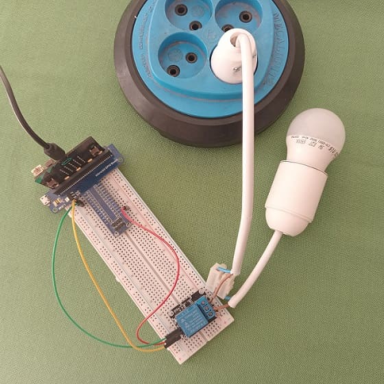
Mounting the Micro:bit board with a lamp
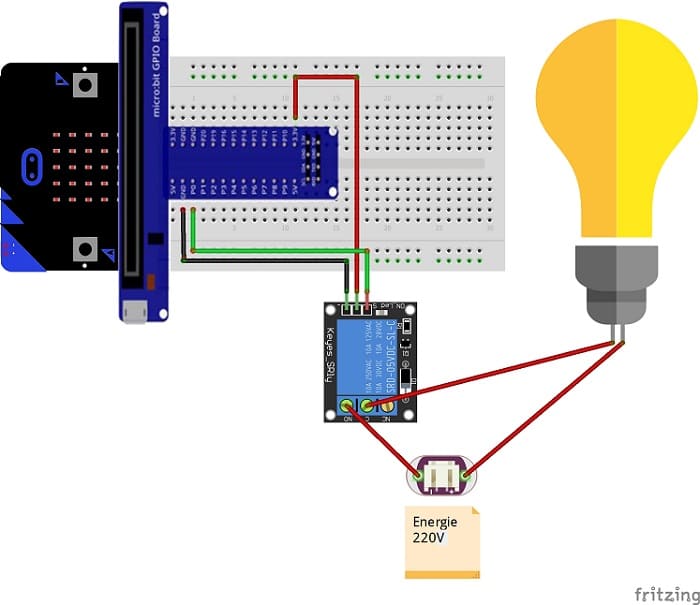
To control a lamp using a Micro:bit board, you will need to use a relay module to safely interface the low-voltage Micro:bit with the high-voltage lamp. Here are the step-by-step instructions to set up the Micro:bit with a lamp:
1- Safety First: Ensure the lamp is disconnected from any power source before proceeding.
2- Connect the Relay to the Micro:bit:
- Connect the relay's control pin (S) to pin P0 of Micro:bit board
- Connect the pin (+) of relay to pin 3.3V of Micro:bit board.
- Connect the relay's ground pin (GND) to the Micro:bit's GND.
3- Connect the Lamp and the power supply to the Relay:
- Connect one of the lamp's wires to the relay's common (COM) terminal.
- Connect the phase (live) wire of the power supply to the normally open (NO) terminal of the relay.
- Connect the neutral wire of the power supply directly to the neutral wire of the lamp.
Blink a lamp by the Micro:bit board
To flash a lamp with the Micro:bit board, you can use the graphical programming language MakeCode. Here are the steps to follow:
1- Access the MakeCode online editor by visiting https://makecode.microbit.org/.
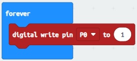
2- Drag the "forever" block from the "Basic" section into the workspace.

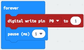
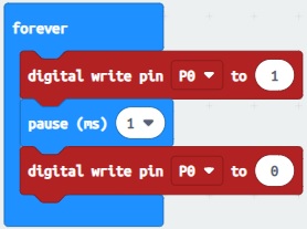
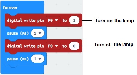
3- Insert the block "digital write pin P0 to 1" from the "Pins" section in the workspace, in the "forever" block to turn on the lamp.
4- Insert a “pause” block from the “Basic” section after the “digital write pin P0 to 1” block.
5- Insert the "digital write pin P0 to 0" block from the "Pins" section into the workspace to turn off the lamp.
6- Insert a “pause” block from the “Basic” section after the “digital write pin P0 to 0” block. Set the wait time depending on how fast you want the lamp to flash.
7- Connect your Micro:bit card to your computer using a USB cable.
8- Click the "Download" button (down arrow) in the lower left corner of the online Makecode editor.
9- Send the .hex file to the Micro:bit card
10- Once the file copy is complete, the lamp will flash according to the wait time set in your program.
Turn on a lamp using the buttons on the Micro:bit board
To turn on a lamp using the buttons on the Micro:bit board, you can follow these steps:
1- Set up the hardware: Connect a lamp to one of the GPIO pins on the Micro:bit board. The most commonly used pin for connecting a lamp is pin 0, which is labeled as "0" on the board. Connect the longer leg (anode) of the lamp to the GPIO pin (e.g., pin 0) and the shorter leg (cathode) to a GND pin on the Micro:bit board.
2- Write the code: Use the Micro:bit's programming environment, such as the MakeCode editor, to write the code. Here's an example code:
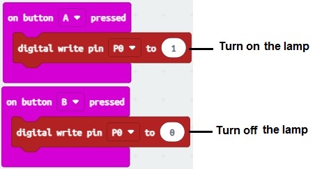
This code listens for button presses on button A and button B. When button A is pressed, it turns on the lamp by setting the GPIO pin (pin 0) to a high state (1). Similarly, when button B is pressed, it turns off the lamp by setting the GPIO pin to a low state (0).
3- Download and flash the code: Connect the Micro:bit board to your computer using a USB cable. Open the MakeCode editor and paste the code into the editor. Click on the "Download" button to download the compiled code onto the Micro:bit. The Micro:bit will appear as a removable storage device. Drag and drop the downloaded file onto the Micro:bit drive to flash the code onto the board.
Once the code is flashed onto the Micro:bit, you can disconnect it from the computer, press the A or B button, and observe the lamp turning on and off accordingly.
0 comment
Leave a comment
Passion for robotics

Recent tutorials
Robotics workshop

Polpular tutorials


Making robots

Most commented tutorials
Robotic arm

Categories
Smart Home