Arduino UNO and 4×4 matrix keyboard
Tutorial plan
1- What is a 4x4 matrix keyboard ?
2- How Arduino UNO displays 4x4 matrix keypad data on LCD screen ?
3- Components Needed
4- Wiring the Components
5- Arduino program
What is a 4x4 matrix keyboard ?
A 4x4 matrix keyboard (or keypad) is an input device consisting of 16 buttons arranged in a grid of 4 rows and 4 columns. Each button is located at the intersection of a specific row and column. Instead of connecting each button with individual wires, the matrix configuration reduces the number of pins needed to detect key presses, making it efficient for microcontroller projects like those with Arduino or ESP32.
How It Works:
- The keypad operates on a grid system where pressing a button connects a row to a column electrically.
- A microcontroller scans the rows and columns:
1. It sets one row to LOW (active) and others to HIGH.
2. It checks the columns to see if a connection (button press) is detected.
3. This process repeats for all rows to identify the specific key pressed.
How Arduino UNO displays 4x4 matrix keypad data on LCD screen ?
The Arduino UNO, in combination with a 4x4 matrix keypad and an LCD screen (with I2C interface), forms an efficient system to capture user inputs (key presses) and display them in real time. Here's a step-by-step explanation of how this process works:
Step 1: Keypad Scanning (Detecting a Key Press)
The Arduino scans the keypad using a technique called "multiplexing":
- It sends a LOW signal to one row at a time while keeping the other rows HIGH.
- Simultaneously, it checks the columns for a LOW signal.
- If a LOW signal is detected on a column, it means a button connecting that specific row and column is pressed.
This process runs rapidly in the background to detect key presses almost instantly.
Step 2: Mapping the Key Press
The Arduino maps the detected row-column combination to a specific character (e.g., 1, 2, A, *).
This mapping is defined in a 2D array in the code, which represents the keypad layout.
Step 3: Sending Data to the LCD
- Once a key is detected, the Arduino uses the I2C communication protocol to send the corresponding character to the LCD.
- The I2C module converts Arduino’s signals to control the LCD using only two pins:
SDA (Serial Data Line) for data transmission.
SCL (Serial Clock Line) for synchronizing the data.
Step 4: Displaying Data on the LCD
The LCD receives the character and displays it on the screen at a specific position (cursor location).
The cursor can be moved programmatically to control where the next character appears (e.g., first line, second line).
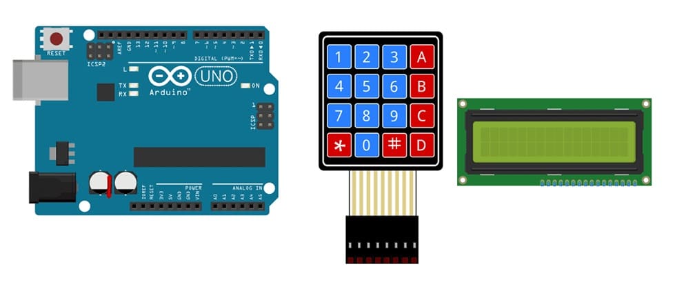
Components Needed
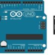
Arduino UNO
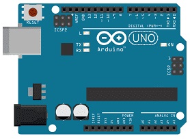
Arduino UNO is a Microcontroller that orchestrates the whole process: reading input from the keypad, processing it, and sending the data to the LCD.
It manages the keypad scanning, character mapping, and LCD communication.
4x4 Matrix Keypad
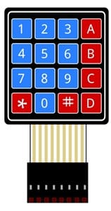
4x4 Matrix Keypad is an Input Device that allows the user to send data by pressing buttons. It’s a compact matrix of 16 buttons arranged in 4 rows and 4 columns.
LCD 16x2 with I2C Module

LCD Screen is an Output Device that displays the data received from the Arduino (such as the pressed key from the keypad).
Wires

The wires connects the components to the Arduino UNO.
Wiring the Components
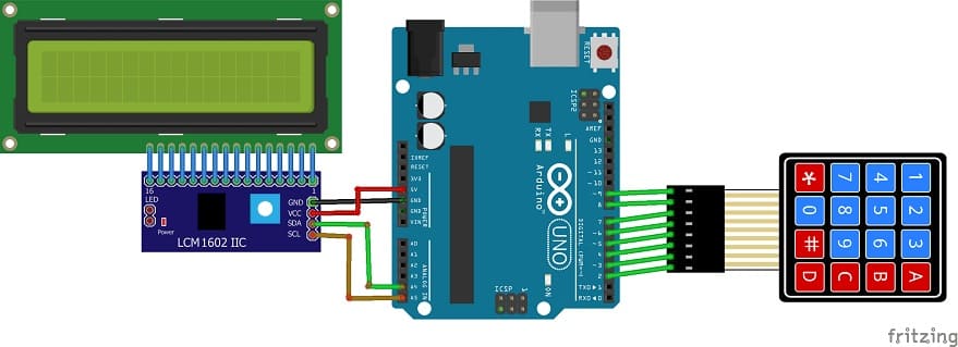
Keypad to Arduino:
R1–R4 (Rows) → Arduino Pins 9, 8, 7, 6
C1–C4 (Columns) → Arduino Pins 5, 4, 3, 2
LCD with I2C to Arduino:
VCC → 5V
GND → GND
SDA → A4 (Arduino UNO)
SCL → A5 (Arduino UNO)
Arduino program
|
1 2 3 4 5 6 7 8 9 10 11 12 13 14 15 16 17 18 19 20 21 22 23 24 25 26 27 28 29 30 31 32 33 34 35 36 37 38 39 40 41 |
#include <LiquidCrystal_I2C.h> // For LCD with I2C module #include <Keypad.h> // For 4x4 keypad // LCD I2C address (often 0x27 or 0x3F depending on the module) LiquidCrystal_I2C lcd(0x27, 16, 2); // Keypad configuration const byte ROWS = 4; // 4 rows const byte COLS = 4; // 4 columns // Keypad layout char keys[ROWS][COLS] = { {'1', '2', '3', 'A'}, {'4', '5', '6', 'B'}, {'7', '8', '9', 'C'}, {'*', '0', '#', 'D'} }; // Connection of keypad to Arduino (adjust if needed) byte rowPins[ROWS] = {9, 8, 7, 6}; // Rows connected to digital pins 9-6 byte colPins[COLS] = {5, 4, 3, 2}; // Columns connected to digital pins 5-2 // Keypad initialization Keypad keypad = Keypad(makeKeymap(keys), rowPins, colPins, ROWS, COLS); void setup() { lcd.begin(16, 2); // Initialize LCD with 16 columns and 2 rows lcd.backlight(); // Turn on the LCD backlight lcd.print("Key Pressed:"); // Display a welcome message } void loop() { char key = keypad.getKey(); // Read the key pressed if (key) { // If a key is pressed lcd.setCursor(0, 1); // Move to the second line of LCD lcd.print(" "); // Clear previous key (overwrite) lcd.setCursor(0, 1); // Reset cursor lcd.print(key); // Display the pressed key } } |
1. Importing Libraries :
|
1 2 |
#include <LiquidCrystal_I2C.h> // For LCD with I2C module #include <Keypad.h> // For 4x4 keypad |
LiquidCrystal_I2C.h: This library simplifies controlling LCDs with I2C. It allows us to send text to the LCD screen using just the I2C protocol.
Keypad.h: This library simplifies interfacing with the 4x4 matrix keypad, handling row-column scanning and key detection.
2. LCD Initialization :
|
1 |
LiquidCrystal_I2C lcd(0x27, 16, 2); |
This line creates an instance of the LiquidCrystal_I2C class and initializes the LCD with an I2C address of 0x27 (this might vary, sometimes 0x3F is used) and a screen size of 16 columns and 2 rows.
The I2C address is unique to each LCD, so it is essential to ensure the correct address (you can often find this in the datasheet or use an I2C scanner to detect it).
3. Keypad Configuration :
|
1 2 |
const byte ROWS = 4; // 4 rows const byte COLS = 4; // 4 columns |
These constants define the number of rows and columns of the 4x4 keypad.
|
1 2 3 4 5 6 |
char keys[ROWS][COLS] = { {'1', '2', '3', 'A'}, {'4', '5', '6', 'B'}, {'7', '8', '9', 'C'}, {'*', '0', '#', 'D'} }; |
This 2D array represents the physical layout of the keys on the keypad. Each button corresponds to a unique character, such as 1, 2, 3, etc.
The structure of the array is:
Row 1: 1, 2, 3, A
Row 2: 4, 5, 6, B
Row 3: 7, 8, 9, C
Row 4: *, 0, #, D
|
1 2 |
byte rowPins[ROWS] = {9, 8, 7, 6}; // Row connections to digital pins byte colPins[COLS] = {5, 4, 3, 2}; // Column connections to digital pins |
These arrays define the Arduino pin connections for the keypad rows and columns. The Arduino will use these pins to scan for key presses.
4. Keypad Initialization :
|
1 |
Keypad keypad = Keypad(makeKeymap(keys), rowPins, colPins, ROWS, COLS); |
This line initializes the keypad using the Keypad class.
makeKeymap(keys): This function creates a mapping between the physical keys on the keypad and the corresponding characters in the keys array.
The rowPins and colPins arrays define the digital pins on the Arduino that are connected to the keypad's rows and columns.
5. LCD Initialization in setup()
|
1 2 3 |
lcd.begin(16, 2); // Initialize LCD with 16 columns and 2 rows lcd.backlight(); // Turn on the LCD backlight lcd.print("Key Pressed:"); // Initial message on LCD |
lcd.begin(16, 2): Initializes the LCD display with 16 columns and 2 rows.
lcd.backlight(): Turns on the LCD backlight to make the display readable.
lcd.print("Key Pressed:"); Displays a welcome message on the LCD.
6. Main Logic in loop() :
|
1 |
char key = keypad.getKey(); // Read the key pressed |
This function checks if any key on the keypad has been pressed and stores the key in the variable key.
|
1 2 3 4 5 6 |
if (key) { // If a key is pressed lcd.setCursor(0, 1); // Move cursor to second line of the LCD lcd.print(" "); // Clear previous key display lcd.setCursor(0, 1); // Reset cursor to second line lcd.print(key); // Display the pressed key on the LCD } |
if (key): This condition checks if a key is pressed (i.e., if the key variable is not NULL).
lcd.setCursor(0, 1): Moves the cursor to the second row of the LCD (row 1, column 0).
lcd.print(" "); Clears the previous key press by printing spaces.
lcd.print(key): Displays the currently pressed key on the LCD.
7. Continuous Loop
The loop() function continuously scans the keypad, and whenever a key is pressed, it updates the LCD to show the corresponding key.
0 comment
Leave a comment
Passion for robotics

Recent tutorials

Robotics workshop

Polpular tutorials


Making robots

Most commented tutorials


Robotic arm

Categories
Smart Home