Door opening control using Micro:bit and 4×3 matrix keypad
Tutorial plan
1- Secure Access System Using Digital Keypad
2- How open a door using Micro:bit and 4x3 matrix keypad ?
3- Required Components
4- Circuit Connections of system
5- Makecode program of system
Secure Access System Using Digital Keypad
A Secure Access System Using Digital Keypad is an electronic locking mechanism that controls entry to a restricted area—such as a room, building, or safe—by requiring the user to input a specific numeric code or password on a keypad. This type of system enhances security by eliminating the need for traditional physical keys, which can be lost, stolen, or duplicated.
Key Features (General Definition):
Digital Keypad: The main interface where users enter a personal identification number (PIN) to gain access.
Control Unit: Processes the input and compares it to a stored password.
Actuator/Lock Mechanism: Activates (unlocks) when the correct code is entered.
Security Measures: May include alarms, time delays, limited attempts, or automatic locking after failed entries.
Power Source: Usually powered by batteries or a direct electrical connection.
Applications:
Home and office door locks
Safes and lockers
Industrial and laboratory access
Smart home automation systems
How open a door using Micro:bit and 4x3 matrix keypad ?
This project demonstrates a digital door lock system that allows secure access through a numeric password entered on a 4x3 matrix keypad. The system is controlled by a BBC Micro:bit microcontroller, which processes the input and operates a servo motor to simulate the opening or closing of a door. An LCD I2C screen provides real-time feedback and instructions to the user.
How It Works
1. User Input via Keypad
The user enters a predefined 4-digit PIN code using the 4x3 matrix keypad. Each key press is detected and displayed briefly on the LCD screen.
2. Micro:bit Processing
The Micro:bit receives the input and checks whether the entered code matches the stored password.
3. Servo Motor Control
If the code is correct, the Micro:bit sends a signal to the servo motor to rotate (e.g., 20°) to unlock the door.
If the code is incorrect, the servo remains in the locked position.
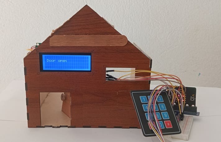
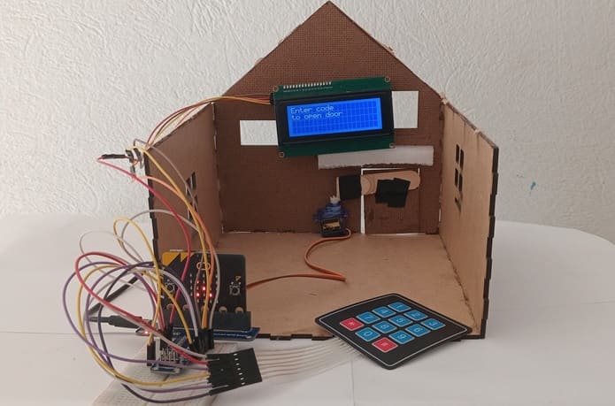
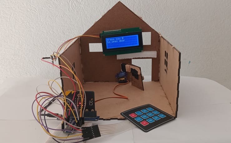
4. LCD Display Feedback
The LCD shows messages like:
"Enter code"
"Invalid code"
"Door closed"
Required Components
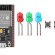
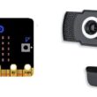
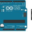
1. BBC Micro:bit (Microcontroller)

The Micro:bit is a compact, beginner-friendly microcontroller developed by the BBC. It serves as the brain of the system, responsible for:
Reading user input from the 4x3 keypad
Verifying the password
Controlling the servo motor to open/close the door
Displaying feedback on the LCD screen
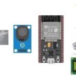
GPIO Extension Card for Micro:bit

GPIO extension card Expands the number of usable input/output pins on the Micro:bit, making it easier to connect multiple components like the RFID reader, LCD, and servomotor.
2. 4x3 Matrix Keypad
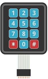
The 4x3 matrix keypad is used as a numeric input device, allowing users to enter a password (e.g., a 4-digit PIN code).
It consists of:
4 rows and 3 columns of buttons
Keys labeled from 0–9, along with “*” and “#” (optional use)
Working Principle:
When a key is pressed, a connection is made between one row and one column.
The Micro:bit scans the rows and columns to detect which key was pressed.
3. Servo Motor (e.g., SG90)
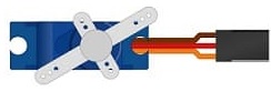
The servo motor acts as the door locking/unlocking mechanism.
It receives a control signal (PWM) from the Micro:bit and rotates its shaft to:
90°: Locked position
20°: Unlocked position
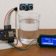
4. LCD Display with I2C Module

The LCD (Liquid Crystal Display) shows system messages to the user, such as:
"Enter code"
"Invalid code"
"Door closed"
Using an I2C interface, it requires only 2 pins from the Micro:bit (SDA and SCL), which simplifies wiring.
5. Breadboard

Breadboard is used for building a non-permanent circuit without soldering.
6. Jumper Wires

Jumper wires (male-to-male or male-to-female) are used to connect components to the Micro:bit.
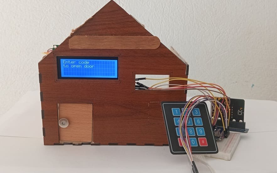
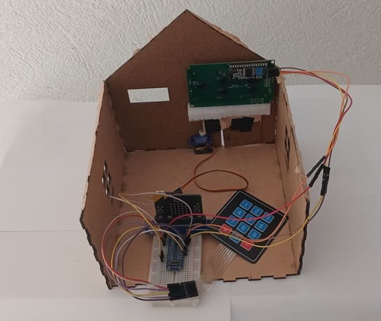
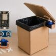
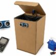
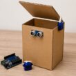
Wooden house prototype
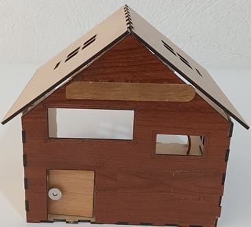
A miniature wooden house represents a real-world structure.
The door mechanism is attached to a servo motor, which rotates to open or close it.
The wooden prototype provides a stable frame for installing components like the IR sensor and LCD screen.
Circuit Connections of system
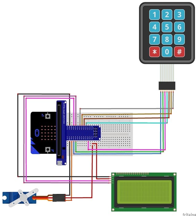
Connection of LCD I2C display to Micro:bit
LCD I2C Pin | Micro:bit Pin |
VCC | 5V |
GND | GND |
SDA | P20 |
SCL | P19 |
Connection of servo motor to Micro:bit
Servo motor Pin | Micro:bit Pin |
Brown wire (-) | GND pin |
Red wire (+) | 5V of GPIO card |
Yellow wire (Signal) | PO pin |
Connection of keypad to Micro:bit
4x3 matrix keypad | Micro:bit |
Pin 1 | P1 |
Pin 2 | P2 |
Pin 3 | P8 |
Pin 4 | P12 |
Pin 5 | Pin 13 |
Pin 6 | Pin 14 |
Pin 7 | Pin 15 |
Makecode program of system
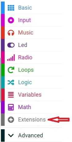
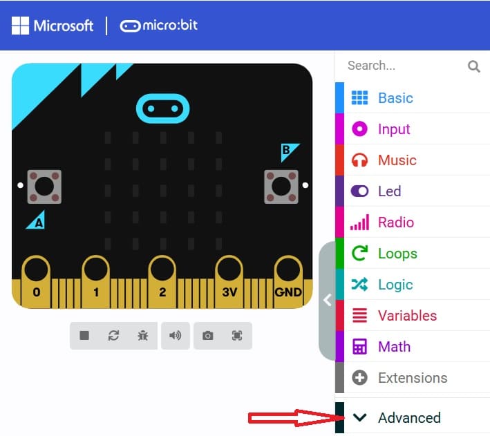
1- Open MakeCode (makecode.microbit.org).
2- Click on Extensions.
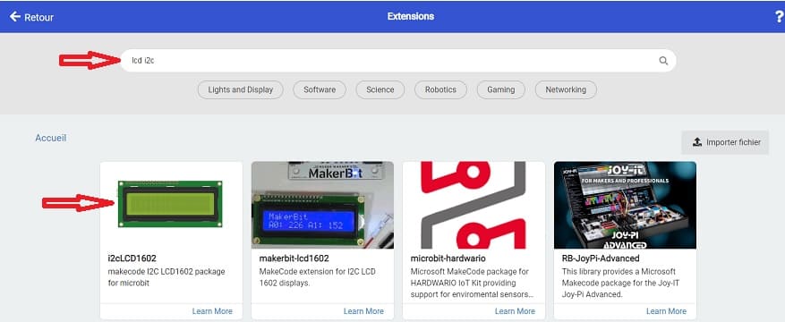
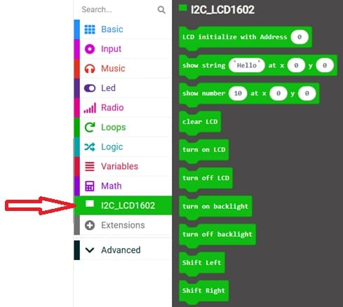
3- In the search bar, type "I2C LCD," and you should find an extension for the I2C LCD display. Add it to your project.
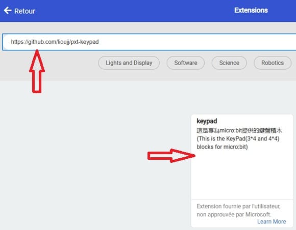
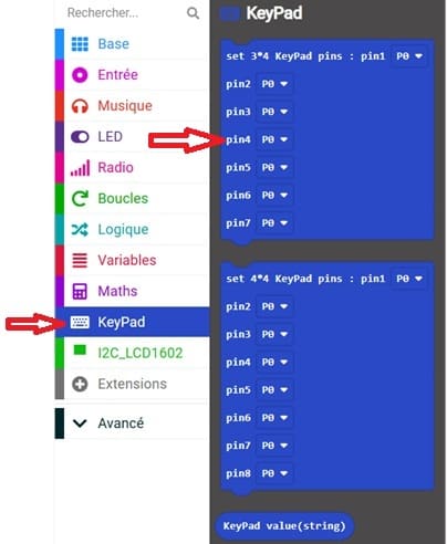
4- In the search bar, type "https://github.com/lioujj/pxt-keypad" and you should find an extension for 4x3 matrix keypad. Add it to your project.
5- Go to advanced :
6- Go to Pin and choose 'servo write pinP0 to 180' instruction :

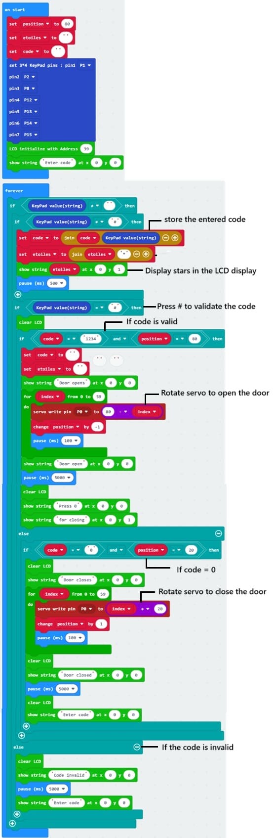
Here is a complete Makecode program with detailed comments for your Smart Door Access Control System
0 comment
Leave a comment
Passion for robotics

Recent tutorials

Robotics workshop

Polpular tutorials


Making robots

Most commented tutorials


Robotic arm

Categories
Smart Home