Remote controlled door system using Arduino
Tutorial plan
1- Remotely control the opening of a door
2- Remotely Controlling the Opening with Arduino
3- Required Components
4- Circuit Connections of system
5- Arduino program to control the system
Remotely control the opening of a door
Remotely controlling the opening of a door using a remote control refers to the ability to unlock or open a door wirelessly using a handheld transmitter device. The remote sends signals to a receiver connected to a door-opening mechanism, such as a servo motor, solenoid lock, or relay-controlled motor.
This system is widely used in home automation, garage doors, electronic gates, smart locks, and secure access control systems.
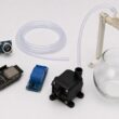
To implement a remote-controlled door-opening system, the following components are required:
1- Remote Control (Transmitter)
Sends a signal when a button is pressed.
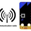
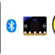
Can use infrared (IR), radio frequency (RF), Bluetooth, Wi-Fi, or Zigbee.
Example: Car key fob, TV remote, RF keychain remote.
2- Receiver Module
Installed near the door.
Receives the signal from the remote and processes it.
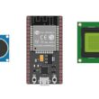
Example: IR receiver module (VS1838B), RF receiver (433MHz MX-05V), Bluetooth module (HC-05), Wi-Fi module (ESP32/ESP8266).
3- Microcontroller (if needed for processing signals)
Processes the received signal and activates the motor or lock.
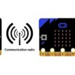
Example: Arduino, ESP32, ESP8266, Micro:bit.
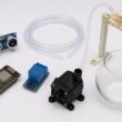
4- Door Opening Mechanism
Servo Motor – Rotates a latch or handle.
Electromagnetic Lock (Solenoid) – Unlocks the door.
Relay-Controlled Motor – Drives an electric motor to open the door.
Remotely Controlling the Opening with Arduino
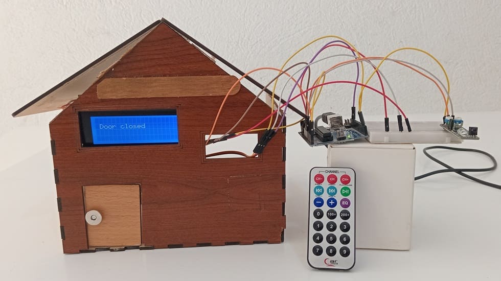
To design a simple automated door system that opens and closes remotely using an IR remote control, with feedback provided on an LCD display. This project demonstrates the principles of embedded systems, sensor interfacing, and actuator control using Arduino.
1. System Startup
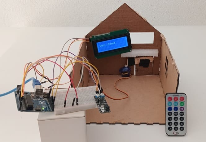
Arduino initializes the servo to the closed position (85°).
LCD shows: “Door is CLOSED”.
2. Waiting for Remote Signal
Arduino constantly monitors digital output of KY-032 sensor.
OUT pin stays HIGH when no IR signal is detected.
3. Remote Signal Detected
User presses a button on the IR remote.
KY-032 detects the IR light → OUT pin goes LOW.
Arduino detects the LOW signal.
4. Door Toggle
Arduino checks the current state:
If door is closed:
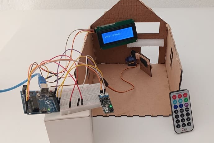
Sends PWM signal to servo → rotate to 20° (open).
Updates door state to open.
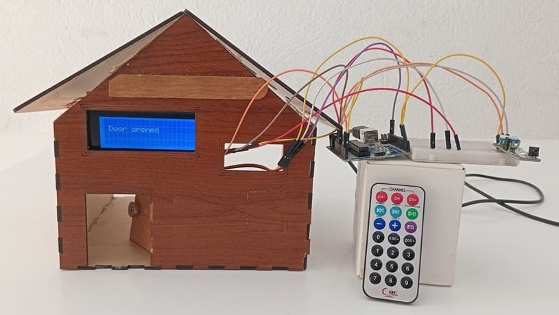
LCD displays: “Door OPEN”.
If door is open:
Sends PWM signal to servo → rotate to 85° (closed).
Updates door state to closed.
LCD displays: “Door is CLOSED”.
5. Repeats Continuously
System stays in loop, waiting for the next IR signal to toggle the door again.
Required Components
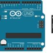
1. Arduino Uno
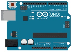
Arduino UNO acts as the brain of the system. It reads input from the KY-032 sensor (triggered by a remote control) and controls the servo motor and LCD display accordingly.
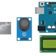
2. KY-032 Infrared Sensor
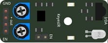
The KY-032 has an IR photodiode and can detect IR light pulses from an IR remote control (depending on configuration). In this system, it acts as a basic IR trigger.
3. IR Remote Control
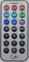
The IR Remote Control Sends infrared signals to the KY-032 sensor to trigger the door mechanism.
4. Servo Motor (SG90 or MG90S)
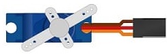
The servo motor opens or closes the door by rotating a shaft (typically 0° for closed, 90° or 180° for open).
5. LCD I2C Display
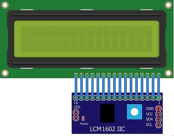
The LCD I2C screen Displays the current status of the door (e.g., "Door Open", "Door Closed").
6. Jumper wires
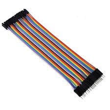
The Jumper wires connect components on a breadboard or directly to the Arduino.
7. Breadboard

The breadboard allows prototyping and easy connection of components without soldering.
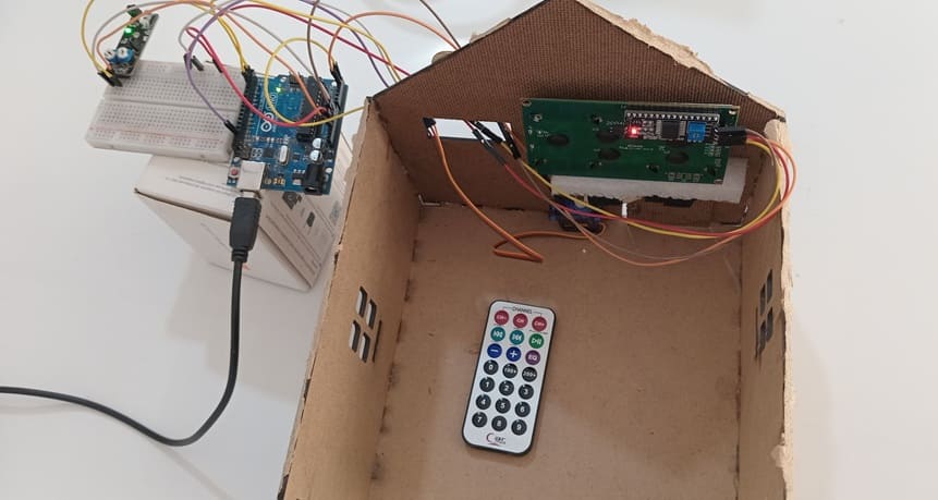
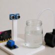
8. Wooden house prototype
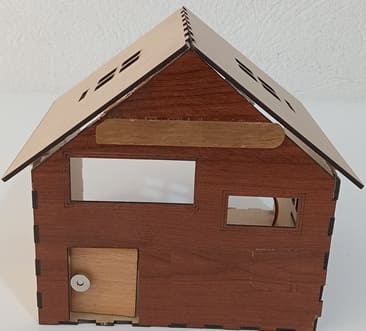
A miniature wooden house represents a real-world structure.
The door mechanism is attached to a servo motor, which rotates to open or close it.
The wooden prototype provides a stable frame for installing components like the IR sensor and LCD screen.
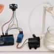
Circuit Connections of system
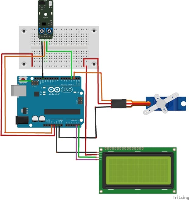
Connection of LCD I2C display to Arduino
LCD I2C Display Pin | Arduino Pin |
GND | GND |
VCC | 5V |
SDA | A4 |
SCL | A5 |
Connection of servo motor to Arduino
Servo motor | Arduino UNO |
Brown wire (-) | GND |
Red wire (+) | 5V |
Yellow wire (Signal) | D2 |
Connection of KY-032 sensor to Arduino
KY-032 senor | Arduin UNO |
GND | GND |
(+) | 3.3V |
OUT | Pin 3 |
Arduino program to control the system
This code uses the LiquidCrystal_I2C and IRremote library for the LCD display.
1- Open Arduino IDE.
2- Go to Sketch → Include Library → Manage Libraries.
3- Search for LiquidCrystal_I2C and install it
4- Search for IRremote and install it
|
1 2 3 4 5 6 7 8 9 10 11 12 13 14 15 16 17 18 19 20 21 22 23 24 25 26 27 28 29 30 31 32 33 34 35 36 37 38 39 40 41 42 43 44 45 46 47 48 49 50 51 52 53 54 55 56 57 58 59 60 61 62 63 64 65 66 67 |
#include <IRremote.hpp> #include <LiquidCrystal_I2C.h> #include<Servo.h> //include the servo library #define IR_RECEIVE_PIN 3 Servo servo; //create a servo object int position_servo = 85; //initial position of the servo LiquidCrystal_I2C lcd(0x27, 40, 4); void setup() { servo.attach(2); //pin used by the servo servo.write(85); lcd.init(); lcd.backlight(); lcd.clear(); lcd.setCursor(1, 1); lcd.print("Door closed"); Serial.begin(9600); // // Establish serial communication IrReceiver.begin(IR_RECEIVE_PIN, ENABLE_LED_FEEDBACK); // Start the receiver } void loop() { if (IrReceiver.decode()) { // Read the KY-032 sensor state Serial.println(IrReceiver.decodedIRData.decodedRawData); if (IrReceiver.decodedIRData.decodedRawData==4077715200){ // If we press the button 1 of remote if (position_servo==85) { // If the door is closed lcd.clear(); lcd.setCursor(1, 1); lcd.print("The door opens"); for (int i=85; i>20 ; i--) { servo.write(i); // rotate the servo motor to open the door delay(100); } lcd.clear(); lcd.setCursor(1, 1); lcd.print("Door opened"); position_servo=20; }} if (IrReceiver.decodedIRData.decodedRawData==3877175040){// If we press the button 2 of remote if (position_servo==20) { // If the door is open lcd.clear(); lcd.setCursor(1, 1); lcd.print("The door closes"); for (int i=20; i<85 ; i++) { servo.write(i); // rotate the servo motor to close the door delay(100); } lcd.clear(); lcd.setCursor(1, 1); lcd.print("Door closed"); position_servo=85; } } IrReceiver.resume(); // Enable receiving of the next value } } |
0 comment
Leave a comment
Passion for robotics

Recent tutorials
Robotics workshop

Polpular tutorials


Making robots

Most commented tutorials


Robotic arm

Categories
Smart Home