Opening a Door with ESP8266 NodeMCU and a Push Button
Tutorial plan
1- How Open a door with ESP8266 NodeMCU and push button ?
2- Required Components
3- Circuit Connections of system
4- Micropython program to control the door
How Open a door with ESP8266 NodeMCU and push button ?
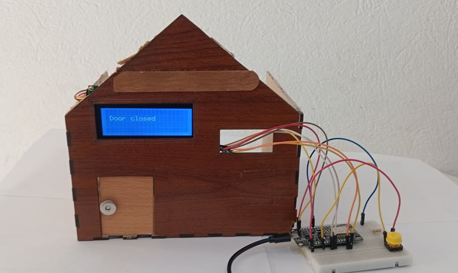
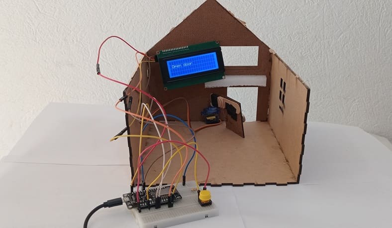
Use a push button to control a servo motor, which acts as a door opener/closer. The ESP8266 NodeMCU controls the logic and updates the I2C LCD display to show the current door status.
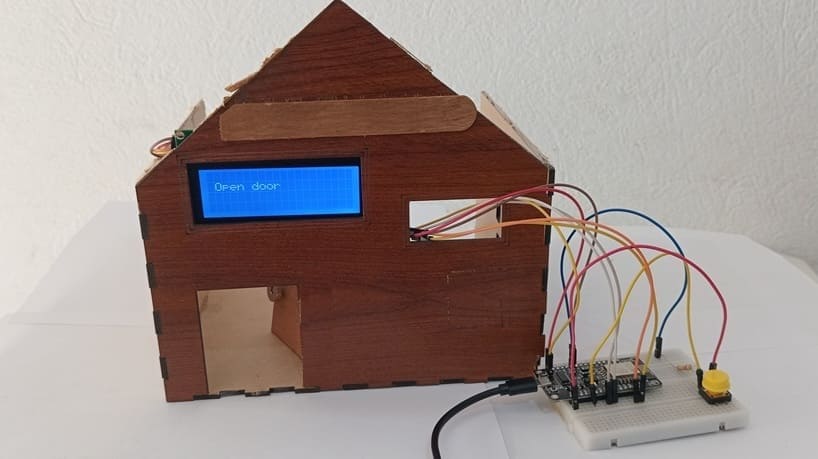
1- When the button is pressed:
The ESP8266 sends a PWM signal to the servo motor to rotate to the "open" position (e.g., 20°).
The LCD I2C screen displays "Door Open".
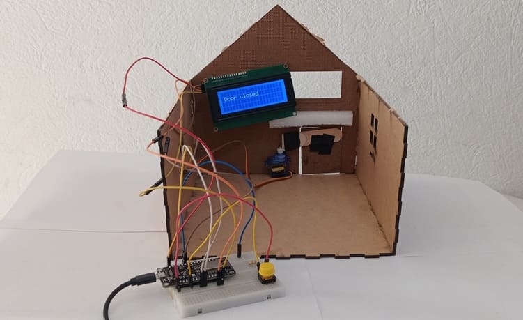
2- When the button is pressed again:
The servo returns to the "closed" position (e.g., 90°).
The display updates to "Door Closed".
3- The state toggles with each press of the button.
Required Components
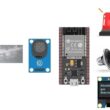
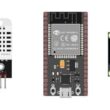
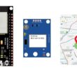
ESP8266 NodeMCU
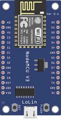
The NodeMCU is a development board based on the ESP8266 Wi-Fi chip. It has multiple GPIO pins that can control various components such as servos and read sensors like buttons.
Role in the Project:
Acts as the central controller
Reads the push button input
Sends PWM signals to the servo motor
Sends data to the LCD display via I2C
Push Button

A momentary tactile switch that makes contact only when pressed.
Role in the Project:
Serves as user input to toggle the door state (open or close)
Connected to a GPIO pin and GND
When pressed, the NodeMCU detects a HIGH signal and reacts accordingly
Servo Motor (e.g., SG90)

A servo motor is a small electric motor with built-in control circuitry to rotate to a specific position between 0° and 180°.
Role in the Project:
Physically opens or closes the door
Receives angle commands (e.g., 0° to close, 90° or 180° to open) from the NodeMCU
LCD 16x2 with I2C Module

A 16-character by 2-line LCD display with an I2C adapter for easy wiring and communication.
Role in the Project:
Displays system status messages:
“The door opens”
“Door Open”
"The door closes"
“Door Closed”
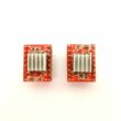
10kΩ Resistor (Pull-down for Button)
![]()
A fixed resistor used to ensure a known voltage level on a GPIO input pin when the button is not pressed.
Role in the Project:
Prevents floating values or false triggering from the push button
Ensures the input pin reads LOW (0V) when button is not pressed
Breadboard

The Breadboard mounts and connect components safely
Jumper wires

The jumper wires establish connections between components and the NodeMCU
Circuit Connections of system
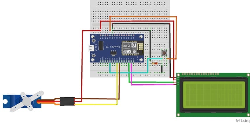
I2C LCD to ESP8266 NodeMCU connections
LCD I2C Screen Pin | ESP8266 NodeMCU Pin |
VCC | VIN |
GND | GND |
SDA | GPIO 4 (D2) |
SCL | GPIO 5 (D1) |
Servo motor to ESP8266 NodeMCU connections
Servo motor | ESP8266 NodeMCU Pin |
Red wire (+) | VIN |
Brown wire (-) | GND |
Yellow wire (Signal) | D5 (GPIO14) |
Push button to ESP8266 NodeMCU connections
1- Connect one leg of the push button to pin D8 (GPIO 15) of ESP8266
2- Put a resistor between the same leg of the push button and the GND pin of ESP8266
3-Connect one leg of the push button to the 3V pin of ESP8266
Micropython program to control the door
Before running the code, install the necessary libraries:
- Servo (for servo motor)
- i2c_lcd and lcd_api for I2C LCD screen
|
1 2 3 4 5 6 7 8 9 10 11 12 13 14 15 16 17 18 19 20 21 22 23 24 25 26 27 28 29 30 31 32 33 34 35 36 37 38 39 40 41 42 43 44 45 46 47 48 49 50 51 52 53 54 55 56 |
import machine from machine import Pin, SoftI2C from time import sleep from servo import Servo from lcd_api import LcdApi from i2c_lcd import I2cLcd # --- I2C LCD Setup --- I2C_ADDR = 0x27 totalRows = 4 totalColumns = 20 i2c = SoftI2C(scl=Pin(5), sda=Pin(4), freq=10000) #initializing the I2C method for ESP8266 lcd = I2cLcd(i2c, I2C_ADDR, totalRows, totalColumns) # --- Push Button Setup --- push_button = Pin(15, Pin.IN) # --- Servo Setup --- motor=Servo(pin=14) motor.move(90) position_door=90 lcd.clear() lcd.move_to(1,1) lcd.putstr("Door closed") # display door closed on LCD I2C display while True: if push_button.value()==1 : # If button is pressed if position_door==90: # if the door is closed lcd.clear() lcd.move_to(1,1) lcd.putstr("The door opens") for i in range(91,19,-1): motor.move(i) # rotate the servo motor to open the door sleep(0.1) position_door=20 lcd.clear() lcd.move_to(1,1) lcd.putstr("Open door") elif position_door==20: # if the door is open lcd.clear() lcd.move_to(1,1) lcd.putstr("The door closes") for i in range(20,91): motor.move(i) # rotate the servo motor to close the door sleep(0.1) position_door=90 lcd.clear() lcd.move_to(1,1) lcd.putstr("Door closed") |
0 comment
Leave a comment
Passion for robotics

Recent tutorials


Robotics workshop

Polpular tutorials


Making robots

Most commented tutorials


Robotic arm

Categories
Smart Home