Automatic door opener with Micro:bit
Tutorial plan
1- What is an automatic door opener ?
2- Functionment of door opener with Micro:bit
3- Required Components
4- Circuit Connections of system
5- Makecode program to control the door by Micro:bit
What is an automatic door opener ?
An Automatic Door Opener is a system that opens and closes doors without manual effort, typically using sensors, motors, or control mechanisms. These systems are commonly found in malls, hospitals, offices, and smart homes for convenience and accessibility.
How It Works:
1- Trigger Mechanism:
- Sensors (motion, infrared, ultrasonic, or RFID) detect a person approaching.
- A button or remote control can also be used.
2- Control Unit:
- Processes signals from the sensor and sends commands to the motor.
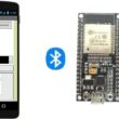
- A microcontroller (like Micro:bit, Arduino, or ESP32) can control the logic.
3- Motor/Actuator:
A servo motor or linear actuator moves the door open or closed.
2- Safety Features:
- Limit switches prevent the door from over-extending.
- Obstacle detection sensors stop the door if something is in the way.
Types of Automatic Doors:
Sliding doors (commonly seen in supermarkets).
Swing doors (open like regular hinged doors).
Revolving doors (often used in hotels).
Garage doors (controlled by remote or sensors).
Functionment of door opener with Micro:bit
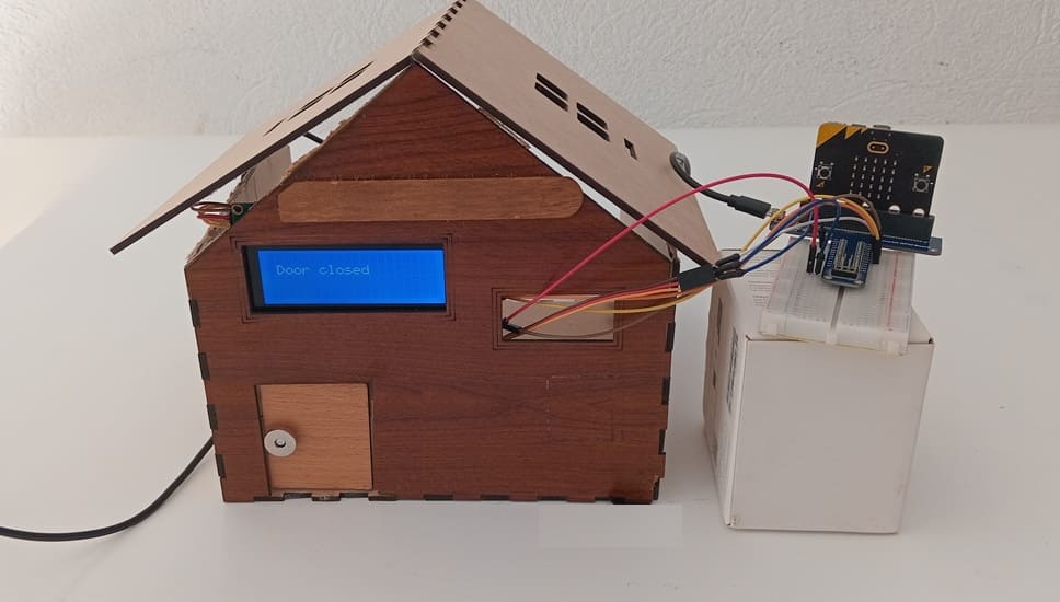
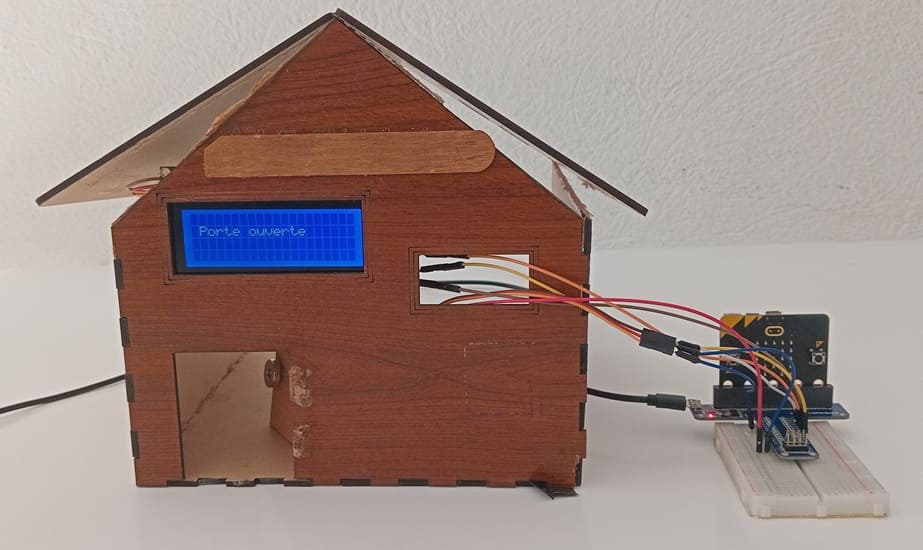
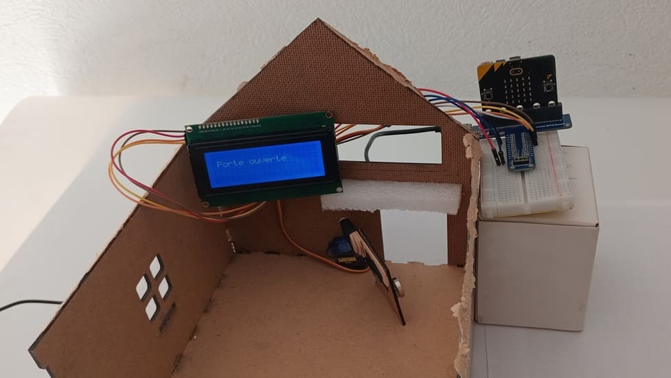
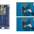
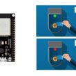
This project uses a Micro:bit, a servo motor, and an LCD I2C screen to manually open and close a door using Button A (Close) and Button B (Open). The LCD screen displays the current status of the door.
Working Principle
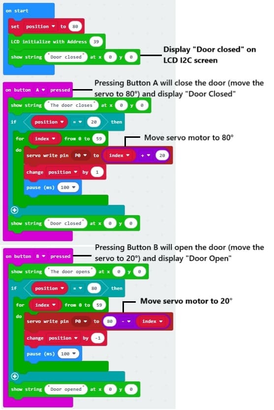
1- The Micro:bit starts with the door closed and displays "Door Closed" on the LCD.
2- When Button A is pressed, the servo moves to 80° (closes the door), and the LCD updates to "Door Closed".
3- When Button B is pressed, the servo returns to 20° (opens the door), and the LCD updates to "Door Open".
4- The system continuously listens for button presses to control the door.
Required Components
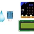
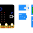
Micro:bit board

The main microcontroller that will control the servo motor and display messages on the LCD.
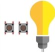
It has two buttons (A & B) for user input:
- Button A: Opens the door.
- Button B: Closes the door.
It Communicates with the LCD over I2C protocol.
It Controls the servo motor via a PWM signal.
GPIO Extension Board for Micro:bit

- Expands the input/output (I/O) capabilities of the Micro:bit.
- Provides header pins to connect the servo, LCD, and other components.
- Ensures easy connections to the breadboard.
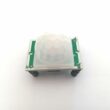
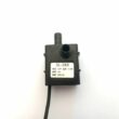
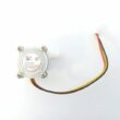
Servo Motor
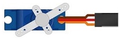
- Used to open and close the door by rotating a small lever or lock mechanism.
- Controlled via a PWM (Pulse Width Modulation) signal from the Micro:bit.
- Rotation angles:
- 80° (closed position)
- 20° (fully open)
LCD I2C Screen (16x2)
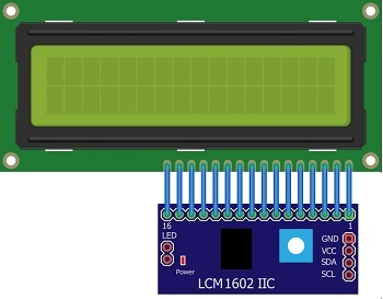
- Displays messages like "Door Open" or "Door Closed."
- Uses I2C protocol (SDA, SCL) to communicate with the Micro:bit.
- Needs an I2C library to function.
Breadboard

- Provides a convenient wiring interface.
- Connects components like the servo motor, LCD screen, and Micro:bit GPIO extension.
- Allows power distribution (5V, GND) to different components.
Wires and Jumpers
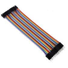
Ensure proper routing of power, ground, and data signals.
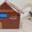
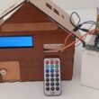
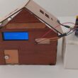
Wooden house prototype
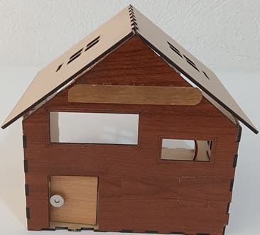
- Represents a real-life house model with a door that opens and closes.
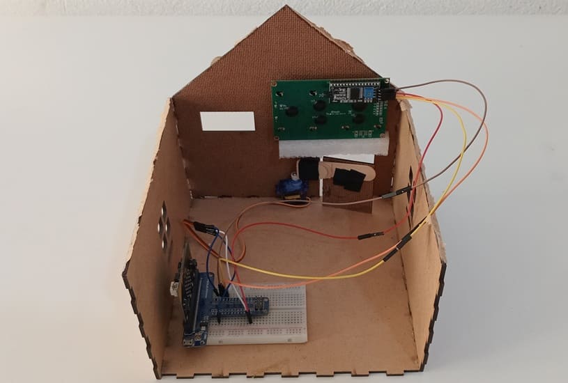
- The servo motor is mounted inside the house, controlling the door movement.
- The LCD screen is attached to the exterior for status display.
- The Micro:bit and electronics are placed inside, acting as the control system.
Circuit Connections of system
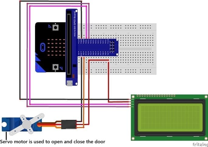
Connection of LCD I2C display to Micro:bit
LCD I2C Pin | Micro:bit Pin |
VCC | 5V |
GND | GND |
SDA | P20 |
SCL | P19 |
Connection of servo motor to Micro:bit
Servo motor Pin | Micro:bit Pin |
Brown wire (-) | GND pin |
Red wire (+) | 5V of GPIO card |
Yellow wire (Signal) | PO pin |
Makecode program to control the door by Micro:bit
1- Open MakeCode (makecode.microbit.org).
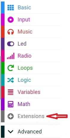
2- Click on Extensions.
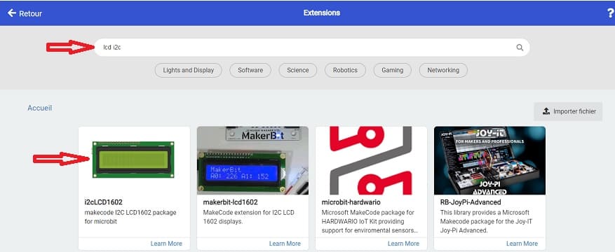
3- In the search bar, type "I2C LCD," and you should find an extension for the I2C LCD display. Add it to your project.
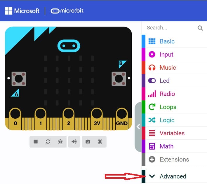
4- Go to advanced :
5- Go to Pin and choose 'servo write pinP0 to 180' instruction :

Here is a MakeCode program for an automatic door opener using a Micro:bit, an LCD I2C display, and a servo motor. The buttons A and B control the servo motor to open and close the door, and the LCD displays the current status.
0 comment
Leave a comment
Passion for robotics

Recent tutorials
Robotics workshop

Polpular tutorials


Making robots

Most commented tutorials
Robotic arm

Categories
Smart Home