RFID based access control system with Micro:bit
Tutorial plan
1- What is an access control system ?
2- Presentation of RFID based access control system by Micro:bit
3- Required Components
4- Circuit Connections of system
5- Makecode program to control our system
What is an access control system ?
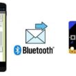
An Access Control System is a security solution that regulates who can enter or access a specific location, resource, or information. These systems are commonly used in buildings, networks, and digital environments to ensure that only authorized individuals can gain access.
Types of Access Control Systems
1- Physical Access Control
Used for doors, gates, offices, and buildings.
Example: RFID card readers, fingerprint scanners, PIN keypads, facial recognition, or smart locks.
2- Logical Access Control
Protects computer systems, networks, and databases.
Example: Passwords, multi-factor authentication (MFA), role-based access, and biometrics.
How It Works
1- Identification – The user presents credentials (RFID card, fingerprint, password).
2- Authentication – The system verifies the credentials against a database.
3- Authorization – If the credentials match, access is granted; otherwise, it's denied.
4- Logging & Monitoring – The system records access attempts for security tracking.
Examples of Use Cases
Office buildings using RFID card access.
Banks requiring fingerprint authentication for transactions.
Online accounts using two-factor authentication (2FA).
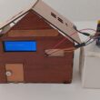
Presentation of RFID based access control system by Micro:bit
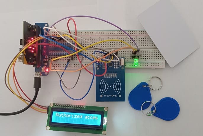
This system uses RFID technology to control access to a secured area. When an RFID card is scanned, the system checks its Unique Identifier (UID) against a list of authorized UIDs. Depending on the result, it provides visual feedback using an LCD display and an RGB LED module.
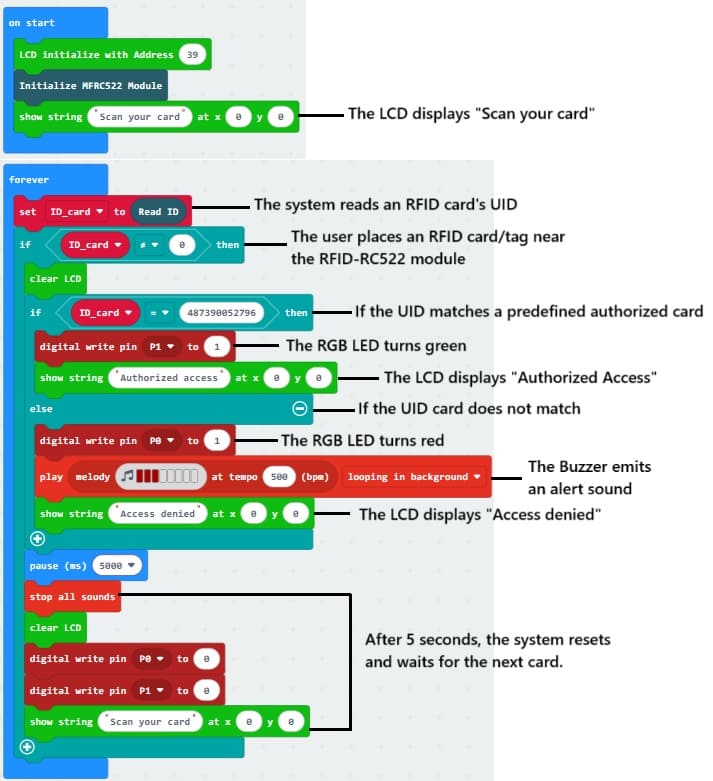
1- System Initialization
The Micro:bit initializes the RFID module, LCD display, and LED.
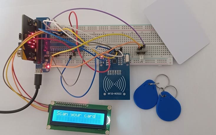
The LCD displays "Scan your card".
2- Scanning an RFID Card
The user places an RFID card/tag near the RFID-RC522 module.
The module reads the UID of the card and sends it to the Micro:bit.
3- Verification Process
The Micro:bit compares the UID with a predefined list of authorized cards.
If the UID matches, access is granted.
If the UID does not match, access is denied.
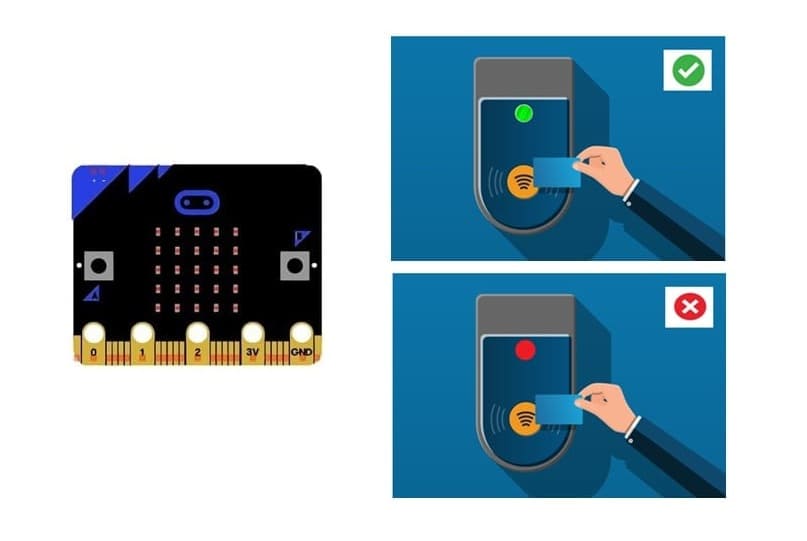
4- Displaying the Result
If authorized:
- The LCD displays "Access Granted"
- The LED turns green
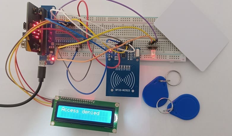
If not authorized:
- The LCD displays "Access Denied"
- The LED turns red
- The Buzzer emits an alert sound
5- System Reset
After 5 seconds, the system resets and waits for the next card.
Required Components
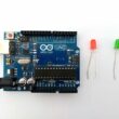
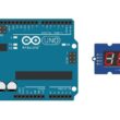
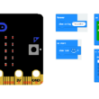
Micro:bit (Main Controller)

The Micro:bit acts as the brain of the system, processing RFID data, comparing card IDs, controlling the LCD display, and changing the LED color.
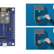
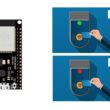
GPIO Extension Card

This card expands the Micro:bit’s limited GPIO pin accessibility, making it easier to connect multiple components.
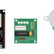
RFID Module (RC522)
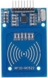
The RFID-RC522 module is responsible for reading the unique ID (UID) of RFID cards or tags and sending it to the Micro:bit for verification.
RFID Card or Tag

![]()
The RFID card stores a Unique Identification Number (UID) that the RFID-RC522 module reads when the card is presented.
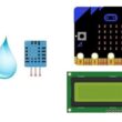
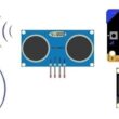
LCD Display
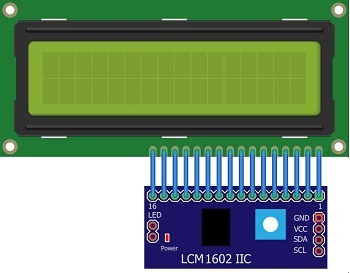
The LCD screen Displays system messages, such as "Access Granted" or "Access Denied".
LED RGB Module
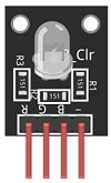
LED RGB module Provides visual feedback by changing colors based on access status:
- Green = Access Granted
- Red = Access Denied
Circuit Connections of system
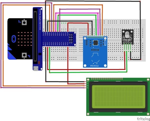
1-FRID-RC522 module connections
RFID-RC522 module Pin | Micro:bit Pin |
VCC | 3V3 |
RST | P8 |
GND | GND |
MISO | P14 |
MOSI | P15 |
SCK | P13 |
SDA | P16 |
2- LCD I2C display connections
LCD I2C Pin | Micro:bit Pin |
VCC | 5V |
GND | GND |
SDA | P20 |
SCL | P19 |
3- RGB LED module connections
LED RGB Pin | Micro:bit Pin |
Red pin | P0 |
Green pin | P1 |
(-) pin | GND |
Makecode program to control our system
1- Open MakeCode (makecode.microbit.org).
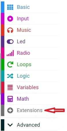
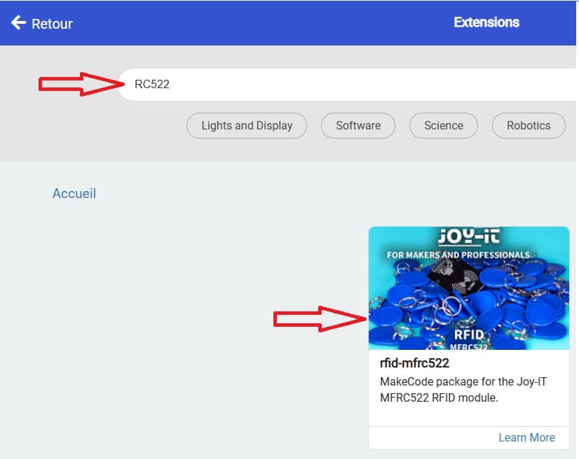
2- Click on Extensions.
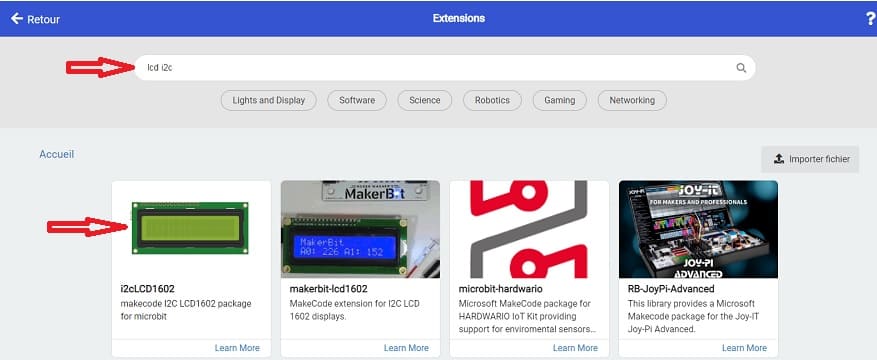
3- In the search bar, type "I2C LCD," and you should find an extension for the I2C LCD display. Add it to your project.
4- In the search bar, type "RC522," and you should find an extension for the RFID RC522 module (for reading RFID cards). Add it to your project.
Here's a Makecode program for an RFID-based access control system using a Micro:bit, an RFID-RC522 module, an LCD I2C screen, and the Micro:bit's built-in buzzer for feedback.
0 comment
Leave a comment
Passion for robotics

Recent tutorials
Robotics workshop

Polpular tutorials


Making robots

Most commented tutorials
Robotic arm

Categories
Smart Home