Read RFID card Data using ESP32 board and RFID-RC522
Tutorial plan
1- Purpose of the tutorial
2- RFID-RC522 module and RFID card
3- Connecting ESP32 board with RFID-RC522 module
4- Micropython code to Read RFID Card and Display on LCD
Purpose of the tutorial
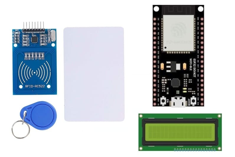
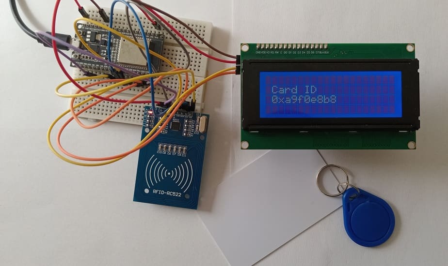
This guide explains how to read RFID card data using an ESP32 board, an RFID-RC522 module, and display the results on an LCD I2C screen. This setup is useful for applications like access control, attendance tracking, and authentication systems.
How RFID Works with ESP32 ?
1- The RFID-RC522 module generates an electromagnetic field.
2- When an RFID tag/card comes close to the reader, it is activated and transmits its UID (Unique Identifier).
3- The ESP32 reads this UID through the SPI communication protocol.
4- The UID is displayed on LCDI2C screen.
RFID-RC522 module and RFID card
1) RFID-RC522 module
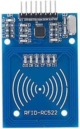
The RFID-RC522 module is a Radio Frequency Identification (RFID) reader based on the MFRC522 chip. It is commonly used for wireless identification, access control, attendance systems, and IoT applications.
a) How RFID Works?
1- The RC522 reader generates an electromagnetic field.
2- When an RFID tag or card enters the field, it gets powered wirelessly.
3- The tag/card sends back a Unique Identifier (UID).
4- The RC522 reads the UID and sends it to the microcontroller (ESP32, Arduino, etc.).
5- The microcontroller processes the UID for authentication, logging, or triggering actions.
b) Applications of RFID-RC522
- Access Control Systems (RFID-based door locks)
- Attendance & Time Tracking (Schools, offices, parking lots)
- IoT Authentication (Smart home & cloud-based security)
- Cashless Payment Systems (MIFARE cards in public transport)
- Inventory Management (Warehouse and asset tracking)
2) RFID card
The RFID-RC522 module operates at 13.56 MHz and supports ISO/IEC 14443A standard RFID cards. Below are the common types of RFID cards and tags that can be used with the RC522 module:
a- RFID badge :
![]()
An RFID badge is a wireless identification card embedded with an RFID chip and antenna, used for authentication, tracking, and security applications. These badges operate at different frequencies and come in various types, depending on security and storage requirements.
b- RFID white card

An RFID white card is a standard contactless smart card that contains an embedded RFID chip and antenna. It is often blank (white), meaning it has no printed design, making it ideal for customization (printing logos, barcodes, or user details).
c- How RFID Badges and cards Work ?
1- The RFID badge contains a unique ID (UID) stored in its embedded chip.
2- When placed near an RFID reader (e.g., RFID-RC522 module), the badge is wirelessly powered by the reader's electromagnetic field.
3- The badge transmits its UID (and possibly additional data) to the reader.
4- The reader sends this data to a microcontroller (ESP32, Arduino, etc.) for verification and processing.
5- If the badge is authorized, it can trigger an action, such as unlocking a door, logging attendance, or granting access to a system.
Connecting ESP32 board with RFID-RC522 module and LCD I2C display
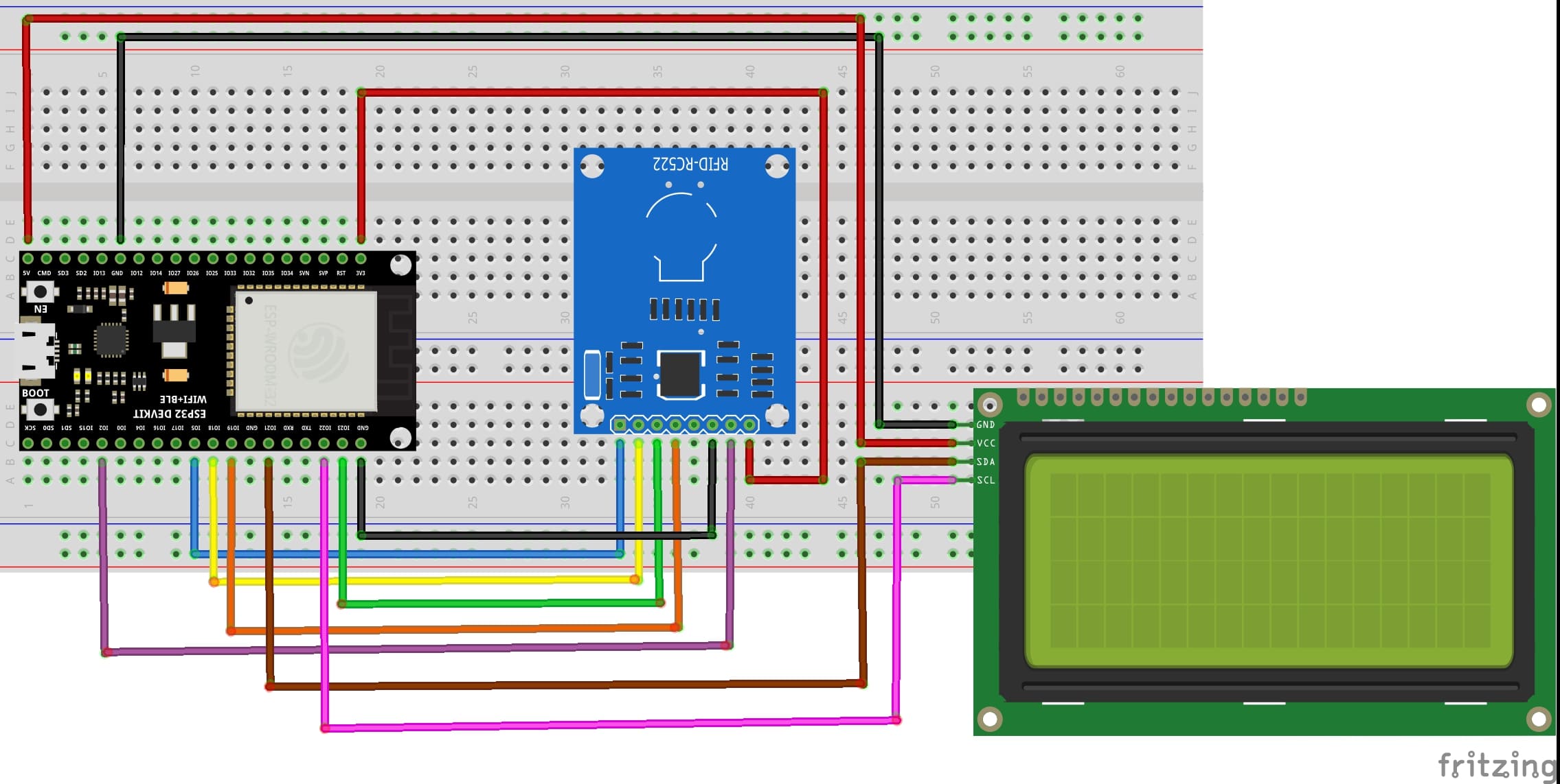
RFID-RC522 to ESP32 Connections
RFID-RC522 Pin | ESP32 Pi |
VCC | 3V3 |
RST | GPIO 2 |
GND | GND |
MISO | GPIO 19 |
MOSI | GPIO 23 |
SCK | GPIO 18 |
SDA (SS) | GPIO 5 |
I2C LCD to ESP32 Connections
LCD I2C Pin | ESP32 pin |
VCC | 5 volt |
GND | GND |
SDA | GPIO 21 |
SCL | GPIO 22 |
Micropython code to Read RFID Card and Display on LCD
Before running the code, install the necessary libraries:
- MFRC522 (for RFID module)
- i2c_lcd and lcd_api for I2C LCD screen
|
1 2 3 4 5 6 7 8 9 10 11 12 13 14 15 16 17 18 19 20 21 22 23 24 25 26 27 28 29 30 31 32 33 34 35 36 37 38 39 40 41 42 43 44 45 46 47 48 49 50 51 52 53 54 |
from time import sleep_ms from machine import Pin, SPI, SoftI2C,ADC from mfrc522 import MFRC522 from lcd_api import LcdApi from i2c_lcd import I2cLcd # Define the SPI pins sck = Pin(18, Pin.OUT) mosi = Pin(23, Pin.OUT) miso = Pin(19, Pin.OUT) sda = Pin(5, Pin.OUT) I2C_ADDR = 0x27 totalRows = 4 totalColumns = 20 # Create SPI object and initialize MFRC522 RFID reader spi = SPI(baudrate=100000, polarity=0, phase=0, sck=sck, mosi=mosi, miso=miso) # Initialize I2C LCD (address 0x27, 20x4 LCD) i2c = SoftI2C(scl=Pin(22), sda=Pin(21), freq=10000) #initializing the I2C method for ESP32 lcd = I2cLcd(i2c, I2C_ADDR, totalRows, totalColumns) def do_read(): while True: rdr = MFRC522(spi, sda) uid = "" <span class="hljs-comment"># Check if an RFID card is present</span> (stat, tag_type) = rdr.request(rdr.REQIDL) if stat == rdr.OK: (stat, raw_uid) = rdr.anticoll() if stat == rdr.OK: # Get the card serial number (UID) uid = ("0x%02x%02x%02x%02x" % (raw_uid[0], raw_uid[1], raw_uid[2], raw_uid[3])) print(uid) lcd.clear() lcd.move_to(1,1) lcd.putstr("Card ID") lcd.move_to(1,2) # Display UID on LCD lcd.putstr(uid) sleep_ms(5000) lcd.clear() lcd.move_to(1,1) lcd.putstr('Scan your card') else: dui="" lcd.clear() lcd.move_to(1,1) lcd.putstr('Scan your card') do_read() |
How the Micropython code works ?
SPI Communication: The ESP32 uses the SPI protocol to communicate with the RFID-RC522 module. We set up the SPI pins using the Pin class from the machine module.
I2C Communication: The LCD is connected to the ESP32 using the I2C protocol. The lcd_api library handles I2C communication for displaying text on the LCD.
Reading RFID Card:
- The rfid.request() method checks for the presence of an RFID card.
- The rfid.anticoll() method reads the UID of the card.
- The UID is displayed on both the Serial Monitor and the LCD screen.
Looping for Card Scans:
The program continuously checks for the presence of an RFID card. When a card is detected, it reads the UID and displays it on the LCD. It waits for 5 seconds before checking for another card.
1 comment

cewek psk jakarta 13-02-2626
My spouse and I stumbled over here coming from a different web page and thought I might check things out. I like what I see so now i am following you. Look forward to going over your web page for a second time.
Leave a comment
Passion for robotics

Recent tutorials


Robotics workshop

Polpular tutorials


Making robots

Most commented tutorials


Robotic arm

Categories
Smart Home