Use a 4×4 matrix keyboard with ESP32 and Smartphone
Tutorial plan
1- What is a 4x4 matrix keyboard ?
2- How ESP32 board send data from matrix keypad to Smartphone ?
3- Components Needed
4- Wiring the Components
5- Programming ESP32 with Micropython
6- Develop mobile application using MIT App Inventor
What is a 4x4 matrix keyboard ?
A 4x4 matrix keyboard (or keypad) is an input device consisting of 16 buttons arranged in a 4-row by 4-column grid. It is commonly used in applications such as calculators, security keypads, and embedded systems for user input.
How It Works
In a 4x4 matrix keypad:
Each button is connected at the intersection of a row and a column.
Rows and columns are connected to the microcontroller through wires or pins.
Pressing a button completes a circuit between a specific row and column, allowing the microcontroller to detect which button was pressed.
How ESP32 board send data from matrix keypad to Smartphone ?
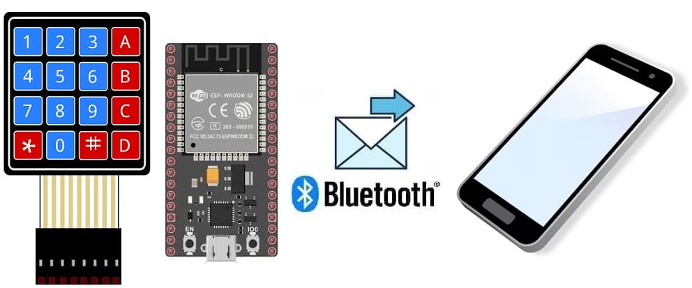
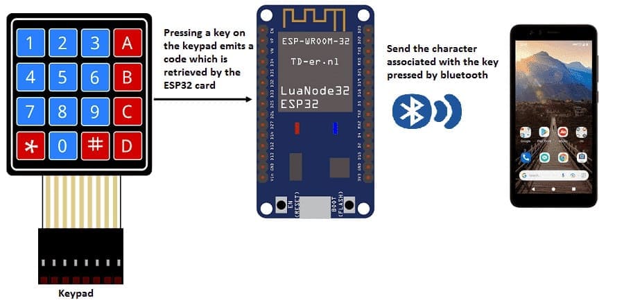
To send data from a matrix keypad connected to an ESP32 board to a smartphone using MicroPython and App Inventor, the process involves three main components:
1. Hardware setup: Connecting the 4x4 matrix keypad to the ESP32.
2. Programming the ESP32 in MicroPython: Scanning the keypad and sending data to the smartphone.
3. Building a smartphone app in MIT App Inventor: Receiving and displaying the data sent by the ESP32.
Components Needed
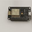
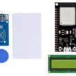
ESP32 Board
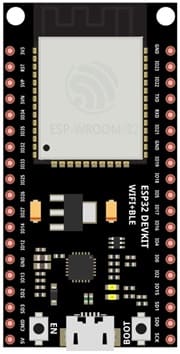
The ESP32 is the microcontroller that handles all the logic and control of the system. It reads input from the 4x4 matrix keyboard, processes the input, and sends the relevant output to Smartphone via Bluetooth.
4x4 Matrix Keyboard
The 4x4 matrix keyboard acts as the input device. It allows the user to press keys to send commands or data to the ESP32. This is typically used for entering PINs, controlling devices, or interacting with the system.
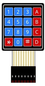
Jumper Wires
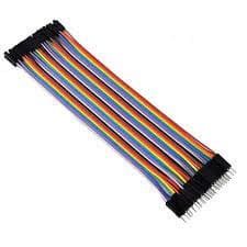
Jumper wires are used to physically connect the ESP32 board and the 4x4 matrix keyboard. These wires transfer electrical signals between the components, allowing them to communicate.
Breadboard:
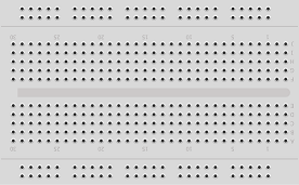
A breadboard can be used to create a temporary circuit for testing and prototyping.
Wiring the Components
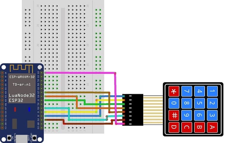
4x4 Matrix Keypad to ESP32:
We connect the 8 outputs of the keypad to the 8 pins of the ESP32 card following this order: D2, D4, D5, D18, D19, D16, D15 and D23.
Programming ESP32 with Micropython
1- Flash your ESP32 with MicroPython using this file esp32-20210902-v1.17.bin.
2- import this three libraries : ble_uart_peripheral.py , ble_advertising.py
3- Code to scan the Keypad and send data to Smartphone :
|
1 2 3 4 5 6 7 8 9 10 11 12 13 14 15 16 17 18 19 20 21 22 23 24 25 26 27 28 29 30 31 32 33 34 35 36 37 38 39 40 41 42 43 44 45 46 47 48 49 50 51 52 53 54 55 56 57 58 59 60 61 62 63 64 65 66 67 68 69 70 71 72 73 74 75 76 77 78 79 80 81 82 83 84 |
from machine import Pin from esp_ble_uart import * from time import sleep import utime import machine import time nom = 'ESP32-ble-uart-gcworks' UUID_UART = '6E400001-B5A3-F393-E0A9-E50E24DCCA9E' UUID_TX = '6E400003-B5A3-F393-E0A9-E50E24DCCA9E' UUID_RX = '6E400002-B5A3-F393-E0A9-E50E24DCCA9E' val_rx = "12" uart = Bleuart(nom, UUID_UART, UUID_TX, UUID_RX) uart.close() WIDTH = 128 HEIGHT = 64 # CONSTANTS KEY_UP = const(0) KEY_DOWN = const(1) keys = [['1', '2', '3', 'A'], ['4', '5', '6', 'B'], ['7', '8', '9', 'C'], ['*', '0', '#', 'D']] # Pin names for Pico cols = [19,16,15,23] rows = [2,4,5,18] # set pins for rows as outputs row_pins = [Pin(pin_name, mode=Pin.OUT) for pin_name in rows] # set pins for cols as inputs col_pins = [Pin(pin_name, mode=Pin.IN, pull=Pin.PULL_DOWN) for pin_name in cols] def init(): for row in range(0,4): for col in range(0,4): row_pins[row].value(0) def scan(row, col): """ scan the keypad """ # set the current column to high row_pins[row].value(1) key = None # check for keypressed events if col_pins[col].value() == KEY_DOWN: key = KEY_DOWN if col_pins[col].value() == KEY_UP: key = KEY_UP row_pins[row].value(0) # return the key state return key print("starting") def rcp_rx(): global val_rx if uart.any(): while uart.any(): val_rx = uart.read().decode().strip() print('sur rx: ', val_rx) # Interruption : affichage donn闁肩厧宕榮 re闁煎墽鎯甧s def env_tx(val_tx): uart.write(str(val_tx) + '\n') print("tx", val_tx) # set all the columns to low init() message="" while True: uart.irq(handler=rcp_rx) for row in range(4): for col in range(4): key = scan(row, col) if key == KEY_DOWN: print("Key Pressed", keys[row][col]) message=message+keys[row][col] env_tx(message) # sending the character associated with the press key to smartphone last_key_press = keys[row][col] time.sleep_ms(1000) |
Develop mobile application using MIT App Inventor
1- Go to MIT App Inventor and create a new project.
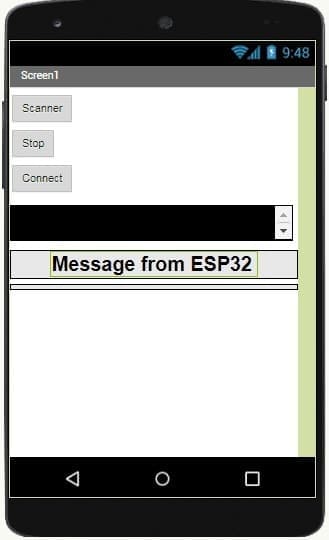
2- Add components:
BluetoothClient: For communication with the ESP32.
ListPicker: To list available Bluetooth devices.
Label: To display received data.
Buttons: For connection and control.
3- Blocks Design:
- Starting with Android 12, Bluetooth permissions have been enhanced to improve security and user data protection. This is why we must declare the authorizations that your application needs in the AndroidManifest.xml file. For Bluetooth, you'll need to include ACCESS_FINE_LOCATION, BLUETOOTH_SCAN, and possibly BLUETOOTH_CONNECT permissions, depending on the features you're using.
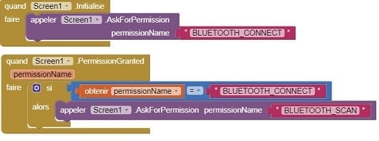
- Use these programming blocks to connect the smartphone to the ESP32 board via Bluetooth:
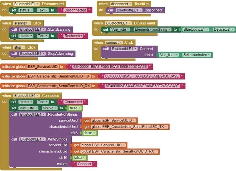
- Use the blocks to capture data sent by the ESP32 and display the data in the Label component.

Download project Download application
Testing the Setup
1- Upload the MicroPython script to the ESP32 using a tool like Thonny.
2- Pair your smartphone with the ESP32 via Bluetooth.
3- Open the app and connect to the ESP32.
4- Press keys on the keypad and see the data displayed on the smartphone app.

