Arduino Line follower robot
Tutorial plan
1- What is line follower robot ?
2- Operation of Arduino Line follower robot
3- Robot components
4- Mounting of robot
5- Arduino program
What is Line follower robot ?
A Line Follower Robot is an autonomous robot designed to follow a pre-defined path, typically a line drawn on a surface. The line is usually black on a white surface or white on a black surface. The robot uses sensors to detect the line and adjusts its movement to stay on the path.
How It Works:
Sensors:
Infrared (IR) sensors or light-dependent resistors (LDRs) are commonly used to detect the contrast between the line and the surface.
Sensors are positioned at the base of the robot to continuously scan the surface.
When a sensor detects the line (high contrast), it signals the controller.
Controller:
A microcontroller (like Arduino, Raspberry Pi, or another embedded system) processes the sensor data and makes decisions.
It calculates how the robot needs to move to stay aligned with the line.
Motors and Actuators:
The robot uses DC motors or servo motors to drive its wheels.
Based on the controller's instructions, the motors adjust the robot's direction.
Algorithm:
A basic algorithm uses conditions like "if left sensor detects the line, turn left; if right sensor detects the line, turn right."
Advanced robots may use PID (Proportional-Integral-Derivative) control to achieve smoother and more accurate line-following.
Operation of Arduino Line follower robot
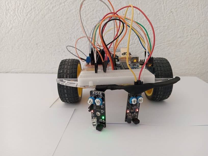
The Arduino Line Follower Robot is a two-wheeled robot designed to follow a predefined path, typically a black line on a white surface or vice versa. Using KY-032 infrared (IR) obstacle detection sensors and L298N driver, the robot can detect the line's position and adjust its movements to stay on track.
How It Works
1- KY-032 Sensors:
The KY-032 emits and detects infrared light. When a black line is detected, less IR is reflected, and the sensor outputs a LOW signal. For a light-colored surface, the output is HIGH.
The sensors are mounted on the underside of the robot, positioned to detect the black line on a contrasting surface.
2- L298N Motor Driver Module:
Controls the two DC motors by enabling forward, reverse, and speed control using inputs from the Arduino.
Receives PWM signals to control motor speeds for smooth turns and directional movement.
3- Arduino:
Processes signals from the KY-032 sensors.
Based on the sensor inputs, decides the robot's motion: forward, left, right, or stop.
Sends corresponding control signals to the L298N motor driver.
Robot components
Arduino UNO:
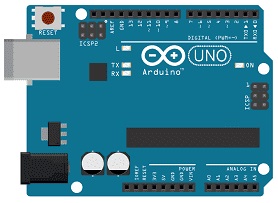
The robot's brain for processing sensor data and controlling movement.
L298N Motor Driver Module:
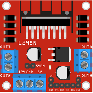
The L298N module is a dual H-bridge motor driver that allows you to control the speed and direction of two DC motors independently. It provides bidirectional control for each motor, making it suitable for driving the wheels of the robot.
KY-032 IR Sensors (x2):

Detect line contrast or obstacles by emitting and detecting infrared light.
Two wheel robot kit
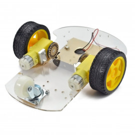
DC Motors with Wheels: Provide movement to the robot.
Chassis: Holds all components together.
Power Source:
Battery pack to power the motors and Arduino.
Jumper Wires:
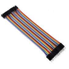
For making temporary connections and wiring between components.
Mounting of robot
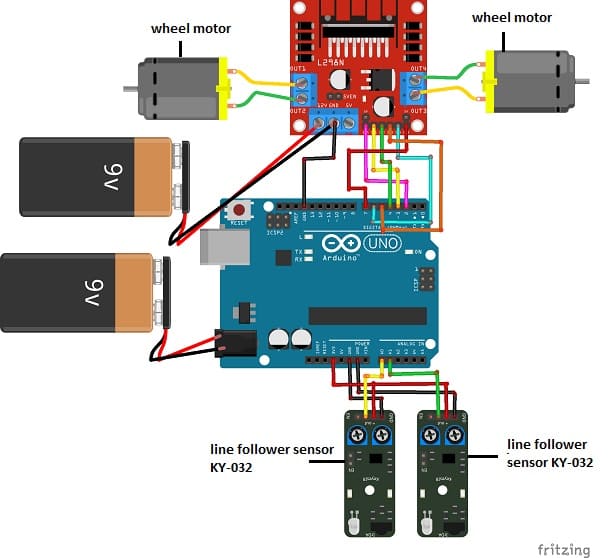
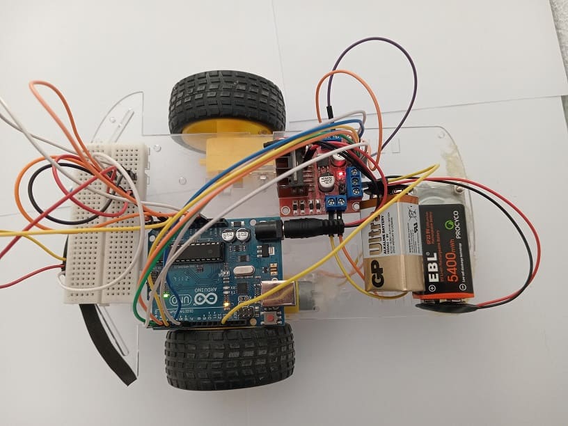
KY-032 Sensors:
VCC → 3.3V (Arduino)
GND → Ground (Arduino)
OUT → Arduino pins (e.g., A0 for left sensor, A1 for right sensor)
L298N Motor Driver to Arduino
IN1, IN2: Control Motor A (left motor). Connect to Arduino digital pins (e.g., D3 and D4).
IN3, IN4: Control Motor B (right motor). Connect to Arduino digital pins (e.g., D5 and D6).
ENA: Connect to a PWM pin (e.g., D2) for speed control of Motor A.
ENB: Connect to a PWM pin (e.g., D7) for speed control of Motor B.
Motor Outputs: Connect Motor A and Motor B to the motor output terminals of the L298N.
Power: Connect a power source (e.g., battery pack) to the +12V and GND pins of the L298N. Use the onboard 5V output to power the Arduino if needed.
Arduino Program
Here is the Arduino sketch to implement the line-following logic:
|
1 2 3 4 5 6 7 8 9 10 11 12 13 14 15 16 17 18 19 20 21 22 23 24 25 26 27 28 29 30 31 32 33 34 35 36 37 38 39 40 41 42 43 44 45 46 47 48 49 50 51 52 53 54 55 56 57 58 59 60 61 62 63 64 65 66 67 68 69 70 71 72 |
// connect motor controller pins to Arduino digital pins // motor one int enA = 2; int in1 = 3; int in2 = 4; int in3 = 5; int in4 = 6; int enB = 7; int capteur_ligne1 = A0; int capteur_ligne2 = A1; int analogVal1,analogVal2; //analog readings void setup() { //Initialize Serial Monitor Serial.begin(9600); analogVal2 = analogRead(capteur_ligne2); // set all the motor control pins to outputs pinMode(enA, OUTPUT); pinMode(in1, OUTPUT); pinMode(in2, OUTPUT); analogWrite(enA, 255); pinMode(enB, OUTPUT); pinMode(in3, OUTPUT); pinMode(in4, OUTPUT); analogWrite(enB, 255); } void loop() { analogVal1 = analogRead(capteur_ligne1); // read the value sent by the left sensor KY-032 analogVal2 = analogRead(capteur_ligne2); // read the value sent by the right sensor KY-032 //Serial.println(analogVal1); //le moteur tourne if(analogVal1<100){ // If the left sensor detects that the robot is going out of line digitalWrite(in3, LOW); // stop the right wheel of the robot digitalWrite(in4, LOW); digitalWrite(in1, HIGH); digitalWrite(in2, LOW); delay(10); //stop le moteur digitalWrite(in1, LOW); digitalWrite(in2, LOW); delay(50); } if(analogVal2<100){ // If the right sensor detects that the robot is going out of line digitalWrite(in1, LOW); // stop the left wheel of the robot digitalWrite(in2, LOW); digitalWrite(in3, HIGH); digitalWrite(in4, LOW); delay(10); //stop le moteur digitalWrite(in3, LOW); digitalWrite(in4, LOW); delay(50); } if ((analogVal1>100)&&(analogVal2>100)) { digitalWrite(in1, HIGH); digitalWrite(in2, LOW); digitalWrite(in3, HIGH); digitalWrite(in4, LOW); delay(10); //stop le moteur digitalWrite(in1, LOW); digitalWrite(in2, LOW); digitalWrite(in3, LOW); digitalWrite(in4, LOW); delay(50); } } |
Robot Behavior
1- Straight Line: Both sensors detect the line (LOW), so the robot moves forward.
2- Left Turn: Only the left sensor detects the line (LOW), causing the robot to turn left.
3- Right Turn: Only the right sensor detects the line (LOW), causing the robot to turn right.
4- Off Track: Both sensors detect no line (HIGH), and the robot stops or adjusts.
