Using Micro:bit Driver Expansion Board to control 5V DC motor
Tutorial plan
1- How the Micro:bit board controls a 5V motor ?
2- Necessary components
3- Wiring diagram of components
4- Makecode program for Micro:bit
How the Micro:bit board controls a 5V motor ?
The Micro:bit board controls a 5V motor using a Driver Expansion Board by leveraging the board's GPIO pins to send control signals. The Driver Expansion Board acts as an interface between the Micro:bit and the motor, providing sufficient current and voltage for the motor to operate, as the Micro:bit cannot directly power the motor due to its low current output.
Advantages of Using a Driver Expansion Board
Current Amplification: Handles higher current than the Micro:bit can provide.
Voltage Compatibility: Supplies the correct voltage to the motor.
Direction Control: Built-in logic to control motor rotation.
Ease of Use: Simple connections and integration with Micro:bit.
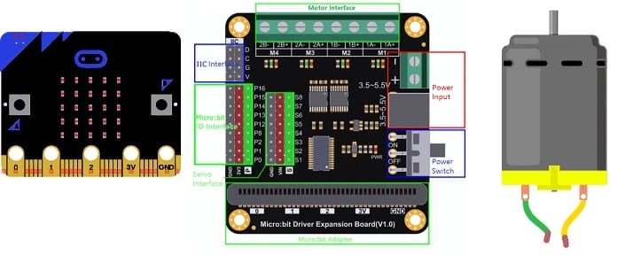
Necessary components
Micro:bit Board:
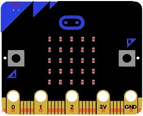
A compact microcontroller with GPIO pins used for sending control signals.
Communicates with the Driver Expansion Board via pins P0, P1, or other PWM-capable pins.
Driver Expansion Board:
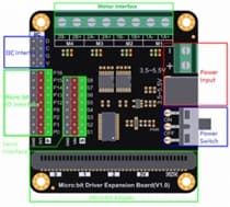
Translates the low-power control signals from the Micro:bit into higher-power signals to drive motors.
Provides separate power input for motors (e.g., 5V or more, depending on the motor).
Includes connectors for easy motor wiring.
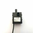
5V Motor:
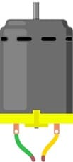
A DC motor that requires 5V power for operation.
Can rotate in forward or reverse directions depending on the control signals.
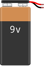
Power Source:
A battery pack or power supply provides sufficient voltage and current for the motor
Wiring diagram of components
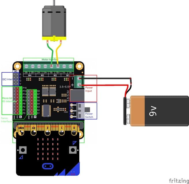
Micro:bit to Driver Expansion Board:
Insert the Micro:bit into the Driver Expansion Board’s slot.
This establishes electrical connections between the Micro:bit’s GPIO pins and the motor driver circuit.
Driver Expansion Board to Motor:
Connect the motor wires to the designated motor output terminals (e.g., M3+, M3-).
For dual-motor boards, use M1 for the first motor and M2 for the second.
Power Supply:
Connect a battery pack (e.g., 6V) or an external power source to the power input terminals of the Driver Expansion Board.
Ensure the voltage matches the motor’s specifications and is within the driver’s operating range.
Makecode program for Micro:bit
1- Go to Microsoft MakeCode and start a new project.
2- In MakeCode, open the Blocks Editor (https://makecode.microbit.org/).
3- Add the Micro:bit Driver Expansion Board extension:
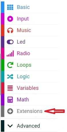
Look for "Extensions" and click on it.
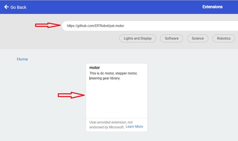
In the search box, insert this link "https://github.com/DFRobot/pxt-motor".
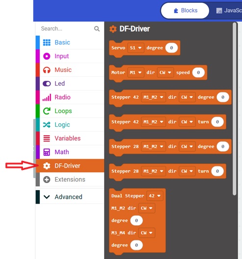
You can now use this blocs to controls the two motors.
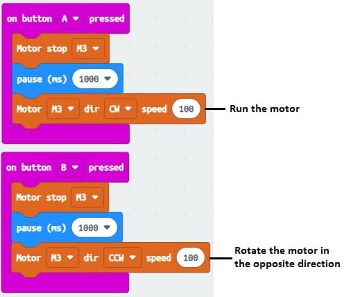
7- Here is the makecode program that that uses the Micro:bit buttons to control a motor :
Depending on which button is pressed:
A pressed → Motor rotates forward.
B pressed → Motor rotates in reverse.
