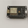
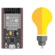
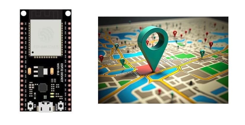
ESP32 board and NEO-M6 GPS module
Tutorial plan
1- Presentation of GPS Trackers
2- Components Needed to realize GPS Trackers with ESP32
3- Circuit Setup
4- Programming ESP32 with Micropython
Presentation of GPS Trackers
A GPS tracker is a device that uses the Global Positioning System (GPS) to determine its location and track movement. Here's a step-by-step explanation of how it functions:
Signal Reception from Satellites
GPS Satellites:
The device communicates with a network of at least 4 GPS satellites. These satellites orbit Earth and send signals containing their location and precise time.
Triangulation/Trilateration:
By calculating the time it takes for signals to travel from satellites to the device, the GPS tracker determines its distance from each satellite. Using this data, it computes its exact position (latitude, longitude, and sometimes altitude).
Processing the Data
The tracker has a GPS receiver that processes the satellite signals to calculate the location in real-time.
The receiver converts raw data into a readable format (coordinates).
Transmitting Location Data
Communication Modules:
Once the location is determined, the tracker transmits this data to a central server or device using communication technologies such as:
Cellular networks (e.g., 3G, 4G, or 5G)
Satellite communication for remote areas
Wi-Fi or Bluetooth for short-range applications.
Monitoring and Tracking
The location data is sent to a monitoring platform such as:
A mobile app
A web dashboard
A computer system
Users can see real-time movement, set geofences (virtual boundaries), or access historical location logs.
Components Needed to realize GPS Trackers with ESP32
Creating a GPS Tracker using an ESP32 board, NEO-M6 GPS module, and an SSD1306 OLED display is a great project.
ESP32 Board:
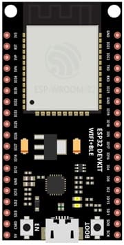
A microcontroller with built-in Wi-Fi and Bluetooth for data transmission.
NEO-M6 GPS Module:
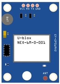
A reliable GPS receiver module for obtaining location data.
SSD1306 OLED Display
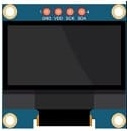
Displays location data (e.g., latitude and longitude) or status information.
Connecting Wires:
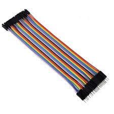
To connect the GPS module to the ESP32.
Breadboard
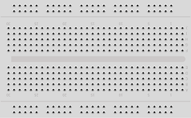
Is a tool for prototyping and testing electronic circuits without soldering.
Circuit Setup
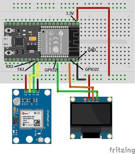
ESP32 to NEO-6M GPS Module
VCC (NEO-6M) → 3.3V or 5V (ESP32)
GND (NEO-6M) → GND (ESP32)
TX (NEO-6M) → RX (ESP32) (GPIO17)
RX (NEO-6M) → TX (ESP32) (GPIO16)
2. ESP32 to SSD1306 OLED Display (I2C)
VCC (SSD1306) → 3.3V (ESP32)
GND (SSD1306) → GND (ESP32)
SCL (SSD1306) → GPIO22 (ESP32) (Default I2C clock pin)
SDA (SSD1306) → GPIO21 (ESP32) (Default I2C data pin)
Programming ESP32 with Micropython
Here’s the complete script to read GPS data and display it on the SSD1306 display:
You need to import these two libraries: ssd1306.py for SSD1306 screen and micropyGPS
|
1 2 3 4 5 6 7 8 9 10 11 12 13 14 15 16 17 18 19 20 21 22 23 24 25 26 27 28 29 30 31 32 33 34 35 36 37 38 39 40 41 42 43 44 45 46 47 48 49 50 51 52 53 54 55 56 57 58 59 60 61 62 63 |
import time import machine from micropyGPS import MicropyGPS from machine import Pin, I2C import ssd1306 #import ssd1306 import _thread import time i2c = I2C(-1, scl=Pin(22), sda=Pin(21)) oled_width = 128 oled_height = 64 oled = ssd1306.SSD1306_I2C(oled_width, oled_height, i2c) oled.text('Carte', 0, 0) # Afficher les deux mots '' oled.text('ESP32', 0, 10) oled.show() def main(): #♦i2c = machine.I2C(scl=machine.Pin(2), sda=machine.Pin(4)) # dsp = ssd1306.SSD1306_I2C(oled_width, oled_height, i2c) uart = machine.UART(1, rx=16, tx=17, baudrate=9600, bits=8, parity=None, stop=1, timeout=5000, rxbuf=1024) gps = MicropyGPS() while True: buf = uart.readline() if uart.any(): for char in buf: gps.update(chr(char)) # Note the conversion to to chr, UART outputs ints normally print('UTC Timestamp:', gps.timestamp) print('Date:', gps.date_string('long')) print('Latitude:', gps.latitude) print('Longitude:', gps.longitude_string()) print('Horizontal Dilution of Precision:', gps.hdop) print('Altitude:', gps.altitude) print('Satellites:', gps.satellites_in_use) print() oled.fill(0) y = 0 dy = 10 oled.text("{}".format(gps.date_string('s_mdy')), 0, y) oled.text("Sat:{}".format(gps.satellites_in_use), 80, y) y += dy oled.text("{:02d}:{:02d}:{:02.0f}".format(gps.timestamp[0], gps.timestamp[1], gps.timestamp[2]), 0, y) y += dy oled.text("Lat:{}{:3d}'{:02.4f}".format(gps.latitude[2], gps.latitude[0], gps.latitude[1]), 0, y) y += dy oled.text("Lon:{}{:3d}'{:02.4f}".format(gps.longitude[2], gps.longitude[0], gps.longitude[1]), 0, y) y += dy oled.text("Alt:{:0.0f}ft".format(gps.altitude * 1000 / (12*25.4)), 0, y) y += dy oled.text("HDP:{:0.2f}".format(gps.hdop), 0, y) oled.show() def startGPSthread(): _thread.start_new_thread(main, ()) if __name__ == "__main__": print('...running main, GPS testing') main() |
Explanation
GPS Parsing
The NEO-6M GPS module outputs raw NMEA sentences (e.g., $GPGGA,...).
The micropyGPS library parses this data to extract:
Latitude and Longitude in degrees.
Timestamp from GPS satellites.
OLED Display
The ssd1306 library is used to interface the OLED display.
Real-time GPS data (latitude, longitude, and time) is updated on the screen every second.

